Gathering can be harmful if power ground is sharing a length with some signal ground.
No sharing is going on (as far as i know, unless by sharing you mean the added length of the L-IN/TT-IN/OUT RCA cables connected to the Rca's GND which i do not see at this point why they are isolated from the case anymore );
The negative gathering exists only in the umbilical; then goes shielded thru a wire at the Phono DC in and electrical ground; and from there to case GND in the same place as the TurnTable ground connector and case.
P.S. I have read the posts about grounding and from what i understand ; i am making a serious grounding error; since the star is used mostly in radio setups; the audio grounding should be a piece of cake (and still i'm not doing it right); especially to remove hum. I am afraid to work with live grounds since an error could lead to a catastrofal failure... sparks and .... rewind ofmost of the setup
") .
. Thanks for the suggestions!!!
I finally powered up this morning for testing but despite Salas' warning I've still managed to switch the polarity of the raw DC-in to one of the channels :-(. Quite how I did this, and then didn't spot it is beyond me.
The fuse blew quickly so I reversed the wires and tried again. Voltages aren't bad: B+ ~34.5V for TP1-TP2 of ~3.6V, with a little difference between channels.
So relieved I hadn't killed the reg I plugged in for a test listen. Sadly it looks like I've killed the audio circuit though. The channel that is working us settling down nicely...
I'm going outside now to give myself a good talking to. I'll need some clear time to troubleshoot but any suggestions where to start looking? Maybe it's easier just to replace all the silicon???
I've attached a photo (hopefully) as we all like to see what others are playing with.
The fuse blew quickly so I reversed the wires and tried again. Voltages aren't bad: B+ ~34.5V for TP1-TP2 of ~3.6V, with a little difference between channels.
So relieved I hadn't killed the reg I plugged in for a test listen. Sadly it looks like I've killed the audio circuit though. The channel that is working us settling down nicely...
I'm going outside now to give myself a good talking to. I'll need some clear time to troubleshoot but any suggestions where to start looking? Maybe it's easier just to replace all the silicon???
I've attached a photo (hopefully) as we all like to see what others are playing with
.Attachments
Thanks Salas. Drop across R11 is pretty similar - 11.82V (good channel), 11.92V (bad channel).
R10 is different though - 24.40V (good), 30.20V (bad). So it looks like I've killed Q4? Perhaps if I ask Tea nicely he might have a replacement.
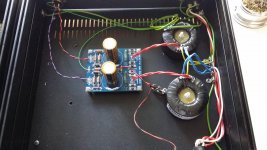
Hopefully some better photos attached this time.
R10 is different though - 24.40V (good), 30.20V (bad). So it looks like I've killed Q4? Perhaps if I ask Tea nicely he might have a replacement.
Hopefully some better photos attached this time.
Attachments
You probably killed Q4. Beyond doubt so much drop across R10 in the bad channel is wrong for this circuit and its Q4 must be replaced anyway even if not burned. The one in the good channel that's pulling for 24V drop is showing correct drain voltage for 8mA IDSS and the R8 R10 values as listed i.e. about 3.5mA pull after the source pin resistor's degeneration effect.
Another easy test you can do before concluding nothing else needs replacement is to compare RDS for all JFETS between the two channels. Q1 VS Q1 and so on. In power off state you measure with the Ohmmeter between drain and source pins for each. No need to remove them from the PCB for that.
Also don't forget to measure drop across R4s and Vbe of Q3s in power on state.
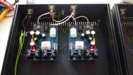
Your construction looks nice in general. Good capacitors also. What type is C3 exactly? Don't know about the ground wiring, seems bit complicated or long. But if it will work with minimal hum so be it. Now you have true repair priorities.
Another easy test you can do before concluding nothing else needs replacement is to compare RDS for all JFETS between the two channels. Q1 VS Q1 and so on. In power off state you measure with the Ohmmeter between drain and source pins for each. No need to remove them from the PCB for that.
Also don't forget to measure drop across R4s and Vbe of Q3s in power on state.
Your construction looks nice in general. Good capacitors also. What type is C3 exactly? Don't know about the ground wiring, seems bit complicated or long. But if it will work with minimal hum so be it. Now you have true repair priorities.
Thanks again Salas, I'll check when I'm back home. C3 are Mundorf Mcap Supreme Evo. They're not great photos - taken on my phone.
The earthing is a bit of a mess and I think I'd do it differently if I were building again. I was trying to ensure all the case pieces were bonded, but it didn't occur to me that the chassis is at circuit ground too. There was a smidge of hum, which could be the earthing, but it could also be the arm wiring which isn't shielded. I might replace the 4 way connectors with five way and have separate chassis earth. One problem at a time.
The earthing is a bit of a mess and I think I'd do it differently if I were building again. I was trying to ensure all the case pieces were bonded, but it didn't occur to me that the chassis is at circuit ground too. There was a smidge of hum, which could be the earthing, but it could also be the arm wiring which isn't shielded. I might replace the 4 way connectors with five way and have separate chassis earth. One problem at a time.
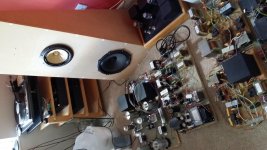
Half right Nico. I can do (almost) what I like if I confine it all to a bedroomSimon,
I take it you are not married and have no children
. The door locks for when little people visit.D3a-2A3 at the top of the photo, 12GN7-GM70 at the bottom, and sneaking in at the right hand side are the PSs for 26-10Y-300BXLS. It's a room to remain sober in.
Okay, I've checked the resistances and voltages and there doesn't look to be anything obviously amiss to me.
Resistances, good channel first:
Q1 13.3 13.2
Q2 13.5 13.2
Q4 37.7 37.3
Q5 39.7 39.7
Q6 34.7 34.8
Q7 71.4 72.7
Voltages, good channel first again:
R4 4.68 4.17
Vbe 0.625 0.622
If Q4 really has died should the resistances be so similar?
Resistances, good channel first:
Q1 13.3 13.2
Q2 13.5 13.2
Q4 37.7 37.3
Q5 39.7 39.7
Q6 34.7 34.8
Q7 71.4 72.7
Voltages, good channel first again:
R4 4.68 4.17
Vbe 0.625 0.622
If Q4 really has died should the resistances be so similar?
RDS is inversely related to IDSS and your FETS matching is very good by that indication.
If only the gate circuit is hit then a FET can bias wrongly while not burned. Also look for possible flux residue around Q4. Feed signal (1kHZ 100mV through 1:100 voltage divider 1K 10R L PAD). Trace the signal path with the scope. See where exactly it stops.
If only the gate circuit is hit then a FET can bias wrongly while not burned. Also look for possible flux residue around Q4. Feed signal (1kHZ 100mV through 1:100 voltage divider 1K 10R L PAD). Trace the signal path with the scope. See where exactly it stops.
i.e. pass 1mV onto the input? Just to be sure (don't want any more damage...)Feed signal (1kHZ 100mV through 1:100 voltage divider 1K 10R L PAD). Trace the signal path with the scope. See where exactly it stops.
Managed a few minutes earlier and traced right back to the collector of Q3 without any signal. My x10 probes aren't sensitive enough to look at Q1 and Q2, but I might try bodging my DMM with a small cap to see if I can pick up any VAC. Another good study of the soldering might be beneficial too.
Does the scope pick the signal before the attenuator for a test? 1st stage in double K369 MC config has >40dB gain. If you feed it 1mV and it works it should show many mV AC across R4 (which is Q3's load). You should also have about 4VDC across R4. Don't forget to select AC coupling at the scope's channel input switch or menu.
No time today sadly. Yes, the scope picks up the signal before the divider, but I couldn't get a signal on the good channel (discernable from the noise of the scope and probe) until the collector of Q3. I'll try again.
At R4 (TP2) I had 4.17VDC but nothing on the scope on the bad channel.
At R4 (TP2) I had 4.17VDC but nothing on the scope on the bad channel.
Last edited:
Finding most signal at Q3's collector (node with R4) its OK because its the top part of the JFET+BJT cascode. If there is >>1mV signal there then the whole first stage works.
Does the bad channel show the expected input load value when you measure across its input RCA with the ohmmeter when the power is off?
Does the bad channel show the expected input load value when you measure across its input RCA with the ohmmeter when the power is off?
- Home
- Source & Line
- Analogue Source
- Simplistic NJFET RIAA