Interconnects are the output wires to the phono which must be shielded but the arm tube has to be grounded also and the cables inside it twisted. If RFI is on the signal cables the mains input filter it does not help. But is the PSU chassis earthed to mains? What helps is 10nF small capacitors from input RCA rings directly to chassis so to ground the RF before it goes further in the zero return route. You may first try put one 100nF across the 10R that parallels the two fat round diodes in the raw PSU board.
the raw psu is earth to mains in its own box/chassis.
"What helps is 10nF small capacitors from input RCA rings directly to chassis so to ground the RF before it goes further in the zero return route."
you mean RIAA input rca? can i use the cap in series to the earth lug in the RIAA box? so, one cap for each rca input?
The TT now:
the channel wires are twisted at least after the tape.
the black wires twisted are from the tonearm and tonearm base.
initially i only had the black wires(tonearm) grounded to the earth and later i connected the chassis TT wire to the earth lug also and nothing changed. The high pitched buzz is there.
i will try the 100nf across the 10r. if unsuccessful maybe the next thing to do is the 10nf at the input RIAA? and then the tonearm wire but for that i have to disassemble the tonearm completely, right?
"What helps is 10nF small capacitors from input RCA rings directly to chassis so to ground the RF before it goes further in the zero return route."
you mean RIAA input rca? can i use the cap in series to the earth lug in the RIAA box? so, one cap for each rca input?
The TT now:
An externally hosted image should be here but it was not working when we last tested it.
the channel wires are twisted at least after the tape.
the black wires twisted are from the tonearm and tonearm base.
initially i only had the black wires(tonearm) grounded to the earth and later i connected the chassis TT wire to the earth lug also and nothing changed. The high pitched buzz is there.
i will try the 100nf across the 10r. if unsuccessful maybe the next thing to do is the 10nf at the input RIAA? and then the tonearm wire but for that i have to disassemble the tonearm completely, right?
Don't disassemble the tonearm before trying other things. One at a time. What happens if you safe lift the fat green mains earth wire from the TT chassis with two anti-parallel diodes for instance. Or what if you just move the shorter blue fat one and the thin black twisted ones along with their TT GND plug to the left away from the mains inlet. Or what if you just dress them much better away as the TT GND output is located now. Secure the fat green mains earth wire to another place more afar like the AC white wires plastic clip screw. But see its sturdy and makes metal contact. Anything changes? Giving a clue?
*Yes I mean Riaa input RCA ring's lug (where you solder the internal wire's shield) ---> 10nF ---> chassis, one each.
But see if its EMI from the mains socket to the TTs grounding wires first because they are very near.
*Yes I mean Riaa input RCA ring's lug (where you solder the internal wire's shield) ---> 10nF ---> chassis, one each.
But see if its EMI from the mains socket to the TTs grounding wires first because they are very near.
i think i'm getting close.
with the TT off, my marantz plays a buzz, just like the RIAA but its only audible when i have my volume high and its more audible in the tweeter speaker. Cant hear low freq. buzz.
now, an interesting thing. when i was moving the wires with my hand to see if the buzz changed, nothing changed, but when i squeezed the wires into each other at the base of the tonearm with my fingers, the buzz gets louder. And when i touch my tonearm or tap it with my hand, i can hear the sound of the tap in my speakers.
does this points to defective tonearm wire shield?
I think I can add my tips too since I was also fighting with humm and ghost noises for a while due to shortcuts to my troubleshooting process and "natural stupidity"  . Many friends here must remember my posts about that subject.
1. I'll go and disconnect amp from phono, and short your amp inputs to see if Marantz is absolutely quite at max volume.
1. If it is quite, connect you phono to Marantz and short phono inputs.
If that tandem is quite at max volume, then your phono and amp is fine.
3. Connect TT with with its GND and disconnected cart leads from your cartridge. You need to short leads there (green to red; white to blue). Test with DVM if you have good conductivity. Move on and if it is quite, then it is your cart has issue. If it is noise, then it is cabling and/or TT-GND all away from cart leads to the phono inputs that you need to test. Also, in that last case, you do not know for sure, but most likely that your cart is fine.
About treatment of noise (in case that your TT GND is done correctly and your cart is fine):
My hizzz was coming from damaged cart (damaged coils). I sent it to repair and guy fixed it. After its installation, I had some high pitch noise and crackling clicks that was RFI. I could hear AM station when I touched TT signal leads at Phono RCAs. That was fixed by installing Ferrite with 3 loops of cable through it close to the input RCA and small caps from input returns to the chassis of phono. Do not remember the exact caps value, but I think it was in pF range, not nF.
Sent from my iPhone using Tapatalk
I forgot to mention that all my steps were guided by gurus here like Salas. Salas, I have 2 of your phonos now (MC and MM) and both are pieces of your art. I wish to have more time to enjoy the clarity of these devices. My Wilson Benesch with MC is sinning and Sonograghe SC-3 TT is with Grace F-9 (MM) is reminds my 80s. Thank you a lot.
Sent from my iPhone using Tapatalk
Sent from my iPhone using Tapatalk
thanks alex...your guidance will help me. i'll report soon
the turntable is a Fujyia and the cart is a pickering V15
https://www.vinylengine.com/library/pickering/v-15.shtml
the turntable is a Fujyia and the cart is a pickering V15
https://www.vinylengine.com/library/pickering/v-15.shtml
There was Lux and there was Seiki and there was Thorens and there was SME (still is). But king of the vintage TT cool was Nak after all? https://www.youtube.com/watch?v=q5O7ssQB4Y8
Yes - the Nak TX-1000 is probably the coolest and rarest of the Japanese engineering statement turntables of the early 80's. It has a measurement device that comes out and measures how off-center the hole in the record was punched, and then moves a pair of eccentric cams in the platter to center the record.
Off-Center eccentricities contribute more to wow than the motor speed variations, by an order of magnitude.
Off-Center eccentricities contribute more to wow than the motor speed variations, by an order of magnitude.
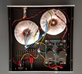
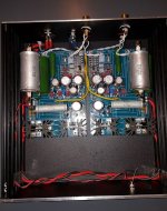
I have resolved my problem in post #16498 by changing Q3z.I get :
Vp1-Vp2: 3,57/3,57 V. I can't obtain 3,6V with one channel but i am very near.
Vrail: 33,67/33,93
V+: 43,46/44,48
I have only one Q6x hot. Is it normal ?
I use a Lenco L75 and Audio Technica AT 150 MLX and the sound is very good.
Very good channel separation. Beautiful voices. Air between instruments. Non-aggressive treble.
Thank you salas
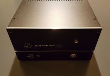
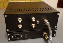
I will post some pictures.
nounouchet
Hi, your build looks very nice. Congratulations. Regarding heat evenness, in this way pcbs are arranged in the box, the two middle ones must feel alike between them and the two outer ones must feel alike between them. If not, measure Vgs (gate to source voltage) and compare between same numbered Mosfets per channel. Let us know those results.
- Home
- Source & Line
- Analogue Source
- Simplistic NJFET RIAA


