Here are some pictures of my at last completes FSP! Installing the front and back panel as well as ground post made the residual noise go away.
I used cat5 wire to internal wiring of the PSF, and the PSU has a dual choke AC input filter.
I used cat5 wire to internal wiring of the PSF, and the PSU has a dual choke AC input filter.
An externally hosted image should be here but it was not working when we last tested it.
An externally hosted image should be here but it was not working when we last tested it.
An externally hosted image should be here but it was not working when we last tested it.
Last edited:
the white sockets are just plastic supports for the transistors and small fets.
the rest of the kit is Michel Orbe, Origin Live modified RB250, Denon DL103, Bryston, PMC OB1s
Barry
Nice gear. But with your C2Y places empty, does it manage to come across balanced in the treble? Transcription geometry and system synergy are big factors in deciding that also of course. And takes some playing time of various records too.
Nice gear. But with your C2Y places empty, does it manage to come across balanced in the treble? Transcription geometry and system synergy are big factors in deciding that also of course. And takes some playing time of various records too.
Hi
I am not sure yet, the sound is still settling down. With some records it is a bit bright in the treble with others it is not.
Barry
")
Beauty ! Congratulations. OK with the sound? Any pictures of the chokes in PSU?
I'll take some pictures later today!
The chokes in the the psu are inside one of those industrial AC filters, it is not a CLC supply.
Here are some pictures of the inside!
The anodizing on hifi2000 cases is quite good so the panels do not conduct at all. As always I had to sand head panel in specific locations so that is conducts quite well and the case (specially the power supply one) is grounded properly!!
An externally hosted image should be here but it was not working when we last tested it.
An externally hosted image should be here but it was not working when we last tested it.
The anodizing on hifi2000 cases is quite good so the panels do not conduct at all. As always I had to sand head panel in specific locations so that is conducts quite well and the case (specially the power supply one) is grounded properly!!
Last edited:
new circuit with no PowerSupply vulnerability, and stable gain
Hello
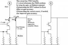
Been tinkering, measuring, designing and analyzing for 50+ year. I offer this circuit approach --- gm device and its Rload, both tied to GND ---- as a way to completely eliminate the VDD as a problem. Of course the "current source" now becomes PSRR limiting factor, but at least Rload no longer directly brings VDD ripple and trash into signal chain.
A second benefit is improved gain-accuracy and gain-stability.
The flatness of device output curves no longer sets the stage gain.
Ideally gain is set by ratio Rsource and Rload, but we know 1/FET_GM is involved. Not having studied the JFET specs, I don't know if there is much tailroom (between GND and Source) for degeneration of large value R.
I suspect not, given the 33ohm values I've seen you homebuilders use.
Lacking a golden ear, but can discern 24 versus 16 bit material if is the AlmanBrothers with guitar decays.
tankcircuitnoise
Hello
Been tinkering, measuring, designing and analyzing for 50+ year. I offer this circuit approach --- gm device and its Rload, both tied to GND ---- as a way to completely eliminate the VDD as a problem. Of course the "current source" now becomes PSRR limiting factor, but at least Rload no longer directly brings VDD ripple and trash into signal chain.
A second benefit is improved gain-accuracy and gain-stability.
The flatness of device output curves no longer sets the stage gain.
Ideally gain is set by ratio Rsource and Rload, but we know 1/FET_GM is involved. Not having studied the JFET specs, I don't know if there is much tailroom (between GND and Source) for degeneration of large value R.
I suspect not, given the 33ohm values I've seen you homebuilders use.
Lacking a golden ear, but can discern 24 versus 16 bit material if is the AlmanBrothers with guitar decays.
tankcircuitnoise
Attachments
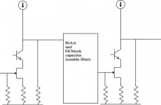
can I ask you to explain what you mean?I offer this circuit approach --- gm device and its Rload, both tied to GND ---- as a way to completely eliminate the VDD as a problem.
Hi, a newbbie questions: Can I use 1000uF for C5 C6 C7 C8 elcaps? This will require any change of resistors values? Cause I already have some 1000uf Silmic II's here...
These caps are in the circuit for what? I noticed that le pacific just don't use any elcap at the circuit. Any problem if I remove C5 and C6 elcaps? Thank you.
These caps are in the circuit for what? I noticed that le pacific just don't use any elcap at the circuit. Any problem if I remove C5 and C6 elcaps? Thank you.
Hi, a newbbie questions: Any problem if I remove C5 and C6 elcaps? Thank you.
They are smoothing capacitors for rail current, C7 also. Removed you will have alot of ripple, to much z out and possible oscillations. C8 is reducing noice from LED bias. Mount as speced, possibly 1000 uF on C6 and C8 if there is room and voltage is no less then 50 V on caps.
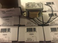
the PSU has a dual choke AC input filter
Here came mine to be PSU filter chokes.
Attachments
I love how mine sound,just wondering ,Can I use the same board to build reel to reel tape amp?NAB or IEC equalization switch build in ?Thank you
Lap
I had made some investigations for such EQ values so have a look there
http://www.diyaudio.com/forums/analogue-source/222113-preamp-reel-reel.html
P.S
Did you put your FSP in ready metal box or you made something custom to compliment the Teres TT looks in the end?
I have a pair of 4700uf to fit near the DC input of the phono boards.
Could I solder these directly to the DC input pads of the phono boards to have some local storage near the regulators?
With the C in the PSU box and the umbilical cable's resistance I would have a sort of CRC PSU before phono boards.
Could I solder these directly to the DC input pads of the phono boards to have some local storage near the regulators?
With the C in the PSU box and the umbilical cable's resistance I would have a sort of CRC PSU before phono boards.
I hope this comparison of NE5532 versus 2SK170 is a useful explanation.can I ask you to explain what you mean?
The primary issues are: Left-Right gain matching, PowerSupply trash, Thermal Distortion/Modulation. [I'll post PSRR results if anyone is interested]
First 3 attachments show NE5532 on GainAccuracy (0.07% at 1KHz), 85dB SNR,and then 4 uV ThermalDistortion at 1volt output[TD is very low because a lowgain Buffer provides the high-current, taking the heat away from the OpAmp's differentialpair. This is not your father's NE5532.].
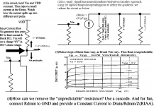
Then 2 attachments discussing the 2SK170 need for Cascoding and ConstantCurrent drive to provide drain Current. The intention is to achieve much more stable gain, so a one-time tweak of the Left_Right balance control is good for all time.
Note in the referred-to-GND circuit that when the FET conducts less current, the current into the Rdrain (the 5Kohm) increases.
Attachments
Last edited:
can I ask you to explain what you mean?
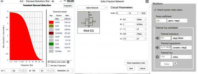
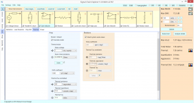
Altered an OpAmp thermal model to better represent the 2SK170, which has larger area, but is a non-differentialpair device as there is no cancelling of local heating effects.
Accordingly, (a)edited the model for 11.4microJoules/degC thermal mass.
And (b) edited Drift from 1uV/degC (suitable for OpAmp) to 1milliVolt/degC (suitable for a single transistor).
Result? given 250uV (moving coil) input, the simulation predicts 12milliVolts thermal distortion for 1.8volts output, or ratio of 150x or 44dB.
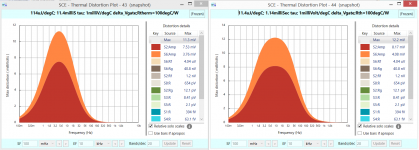
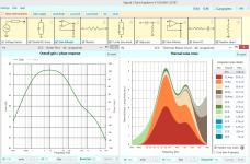
Attachment1 shows the thermal distortion for 2 different thermal masses. Note the peak frequency changes (by sqrtroot of mass change).
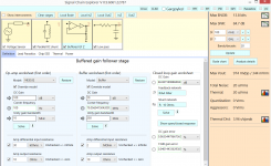
Attachment2 shows the signalChain (pretty much a Salas topology shoehorned into an OpAmp-oriented simulator) predicting 78dB SNR and Vout of 1.8volts.
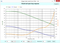
Attachment3 shows the BODE and the various thermal noise contributors.
Attachments
- Home
- Source & Line
- Analogue Source
- Simplistic NJFET RIAA