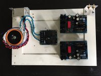
Fitted resistors my rails are 35v each but to get 3.6v at tp1 tp2 I had to lower so I have 34v with 3.6v and 33.3v with 3.6v and all looks good
On to the last part vr1 I have read the guide lots but I do not understand ,unless you mean while music playing ?
A big thank you Salas
On to the last part vr1 I have read the guide lots but I do not understand ,unless you mean while music playing ?
A big thank you Salas
Having bit different optimum rails between channels is normal and reflects the little different bias needs of the various close but never 100% close JFETS. VR1 is like a half circuit vernier for VR2. Its able to alter the input stage's rail level only. You can use it for help in bias or not, I would say only if the main rails in the two channels tend to go grossly apart for correct TP, but the bulk of adjustment must come from VR2.
What do you think of orange drop pp's soundwise?
Good tone, not intruding, but not the last word in resolution either. Great for the price though. Nice pilot cap.
So I finally got everything together and powered up. With 27Vdc on the rail TP1 is 7.9V.
R2,3 should have been closer to 9r but 10r was the closest available in TNPW.
Q1,Q2 were labeled 13.84.
7.9V across four leds
R13 1.2k with Q1,2 populated.
Now for the big questions........
If I replace R2,3 with 9r will TP1 become adjustable within the recommended 3.6V range?
What does VR1 resolution adjustment do?
Thanks
Attachments
Last edited:
You don't want TP1 3.6V, you want TP1-TP2 to be 3.6V. TP1 is the positive end of the chain of 4 LED's, so it is 7.9V above ground. TP2 is the junction of R14 and R4 (took me forever to find it), it is the voltage on the collector of Q3. The 3.6V measurement is the base-collector voltage on Q3.
Your rail voltage seems low.
Your rail voltage seems low.
The build guide for this circuit says the rail voltage should be ~35V. Many of us have found it needs to be a little lower, like 32-33V. Where did you see 24-27V rails?
VR1 basically gives you finer control over front-end rail voltage to get the TP1-TP2 voltage right. If TP1-TP2 is 7.9V (TP1 higher), and your string of 4 LEDs is 7.9V, then the junction of R4/R14/Q3 collector is at 0V. I will let someone smarter than me figure out what that means. Either way I'm pretty sure your rail voltages are too low.
VR1 basically gives you finer control over front-end rail voltage to get the TP1-TP2 voltage right. If TP1-TP2 is 7.9V (TP1 higher), and your string of 4 LEDs is 7.9V, then the junction of R4/R14/Q3 collector is at 0V. I will let someone smarter than me figure out what that means. Either way I'm pretty sure your rail voltages are too low.
- Home
- Source & Line
- Analogue Source
- Simplistic NJFET RIAA

