32.6V is normal since R2, R3 are now slightly high.
The transformer isolates and makes the TT cable run balanced as the cart coils allow, if its of the balanced impedance floating primary kind so it gets rid of interference on the TT cable. Also it usually has less bandwidth than the electronics and filters RF. After trying 1uH coil even, I tend to think the problem is less relative to what you do at the phono side of things. What about the woofing? That stopped too, seeming related? Was there any interference hint before changing the internals of your cart? Since your X5 SUT does not overload the high sensitivity FSP version (proves quite good margin in practice for that) and solves weirdness in your installation, why not leave it in. If there is no compromise in the transparency department that you can feel, surely.
Thank you for clarification. Yes, it is definitely TT related issue and not FSP setup or matching. It is also not my new rebuild cart (the old one has the same issue) and not the cable since RF and noise gone when I shorted cart side colored cable leads. It might be some issue inside carbon tube (my arm), but I can’t check it out. It is sealed.
I do not feel that my sound got some change when I connected that trany. All clarity of High End is still there. I have nice Stevens & Billington trany, so do not anticipate any issue with it.
I will integrate these step-us tranys and headache will be cured.
Sub behave did not change either and on the same volume level loudness its do have seismic behave. My Linkwitz filter is almost ready and I’ll test it soon. Actually the filter is ready and I need to build PSU for test. Do you know how quite should be PSU for such opamps filets?
Normal chip reg PSU will suffice for a subsonic op amp filter. LM78XX is simplest. PSRR of op amps is very high in low frequencies and no tonality worries for subs also.
Got it. Than you.
Anyway I need one like this PSU for my "lab".
P.S. What is the exact model of your SUT if you remember? Also no interference is picked from the cable between SUT and FSP now that it is still outside the box, so again nothing appears problematic to solve towards the phono side.
Though question…. I obtained two sets once, about 4 years ago. One set is 1:5 and second is combo 1:10 with 1:20, depend to wiring.
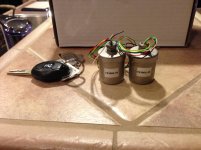
If I’m not mistaken, it was TX1003-5 (x5) and TX1003-10 (x10 and X20) cupper and I purchased them directly from Stevens & Billington UK. I paid about $185 for a pair and friend of mine helped me to get them as for a dealer price.
No any interference, but these cables from SUT to FSP are very sensitive. They behave like microphone when I touch them or bump gently. I'll report when these tranys will be in the box with FSP. Lets see then...
Attachments
Last edited:
Those are very good make. Among the very best. Fully symmetrical also. If there is an electrostatic shield wire, that should go to FSP signal ground along with secondary's cold.
They sent me some connection instructions back then with tranys and they mentioned to connect all GNDs to chassis GND with the electrostatic shield. So, you recommend to connect only Output GND to Chassis and not to connect input GND?
Attachments
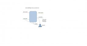
That's an SE grounded transfer scheme. I think if you will connect green to any electronics GND you will lose the balanced signal travel benefit from cart pins to the transformer's input. This SUT model is most probably symmetrically wound inside. I would start with red & green input twisted pair to TT floating (RCA in), yellow & blue to FSP pcb twisted pair, (blue to input GND its already referenced to chassis), to keep interference pick up areas tight. Then the black to chassis lug. If noises happen, in case there is a reason inside we don't know about this step up, you do what is in the photo. No big deal revising connections on trial after the mechanical installation is done which is the bulk of the job.
Tried all ways and no input GND either output GND connect to chassis GND is the most quite way to connect these tranys. I connected electrostatic shield and transformers cans-containers to chassis GND and that is it. Very quiet now and I’m happy.
BTW, my bass on my loudspeakers (not on subwoofer) improved quite significantly when I connected system via these tranys.
BTW, my bass on my loudspeakers (not on subwoofer) improved quite significantly when I connected system via these tranys.
Hi Nick,
If I’ll ever decide to replace my C3 (currently installed - 0.1uF Mundorf S&O) with the lower value cap (let’s say 0.047uF or 0,022uF) then what brand would be the best match for synergy with C4 2.2uF Mundorf S&O. Unfortunately, Mundorf does not manufacture these values in Supreme product line. Thank you.
If I’ll ever decide to replace my C3 (currently installed - 0.1uF Mundorf S&O) with the lower value cap (let’s say 0.047uF or 0,022uF) then what brand would be the best match for synergy with C4 2.2uF Mundorf S&O. Unfortunately, Mundorf does not manufacture these values in Supreme product line. Thank you.
0.047u is in range, 0.022u is special occasion for helping reduce woofing problems if no other subsonic filtering is available. Can alter the low mids tone to thinner under normal circumstances.
Teflon starts to get rather tempting in such small values. Clarity MR is available in those values too. Both choices will suite, matching % is irrelevant in that position.
Teflon starts to get rather tempting in such small values. Clarity MR is available in those values too. Both choices will suite, matching % is irrelevant in that position.
No, I realized that I need to use it just in case of special circumstances. I asked "just in case of...".
I can test my linkwitz yet. I‘m awaiting for PCB for PSU. It is nice since it has space for trany on it. Space is critical for my integration into sub.
Power Supply PCB for Mini Pre Amps · P N 63208 B | eBay
I'll might get it tomorrow.
I can test my linkwitz yet. I‘m awaiting for PCB for PSU. It is nice since it has space for trany on it. Space is critical for my integration into sub.
Power Supply PCB for Mini Pre Amps · P N 63208 B | eBay
I'll might get it tomorrow.
I presume you guys run your 'Simplistic' phono stage modules through a quick frequency generator / CRO test before you install it in the case and attach the input/output RCAs?
For those that have, I'm interested to know whether you have ever experienced the following situation (this is not on a 'Simplistic' but a similar circuit which is battery powered - 2x 12v SLAs each channel):
1. I put 1KHz into each module in turn and look at the output on the CRO screen - a lovely smooth sine wave.") Then I note the output level, so I can adjust each module to get them producing the same output.
Then I note the output level, so I can adjust each module to get them producing the same output.
2. Then I install them in the case and connect up the input/output RCAs etc. Now, after connecting everything up I again use my sig-gen and CRO ... and I get what I call "dancing sine waves" - there are several of them and they jump up and down on the CRO screen!
This suggests to me that somehow I now have some instability - but listening to the phono stage doesn't reveal any nasty behaviour. So I am perplexed as to:
* what is causing these "dancing sine waves",
* why can't I hear any negative influence on the sound (with this instability), and
* how can I get rid of the instability?
Hence my interest in feedback from 'Simplistic' builders. (Before anybody asks - yes, I do have a 100ohm Gate stopper in front of each JFET gain stage.)
Thanks,
Andrew
For those that have, I'm interested to know whether you have ever experienced the following situation (this is not on a 'Simplistic' but a similar circuit which is battery powered - 2x 12v SLAs each channel):
1. I put 1KHz into each module in turn and look at the output on the CRO screen - a lovely smooth sine wave.
Then I note the output level, so I can adjust each module to get them producing the same output.2. Then I install them in the case and connect up the input/output RCAs etc. Now, after connecting everything up I again use my sig-gen and CRO ... and I get what I call "dancing sine waves" - there are several of them and they jump up and down on the CRO screen!
This suggests to me that somehow I now have some instability - but listening to the phono stage doesn't reveal any nasty behaviour. So I am perplexed as to:
* what is causing these "dancing sine waves",
* why can't I hear any negative influence on the sound (with this instability), and
* how can I get rid of the instability?
Hence my interest in feedback from 'Simplistic' builders. (Before anybody asks - yes, I do have a 100ohm Gate stopper in front of each JFET gain stage.)
Thanks,
Andrew
- Home
- Source & Line
- Analogue Source
- Simplistic NJFET RIAA