Between 0.5mA dif in buffers not really noticeable. Although matching is always nice. Its for the peak mA ability and gm, no gain mismatch worries. Peak ability is very near, gm even nearer for 0.5mA dif in fets. 15mA swing from 7.5mA resting point across 20K load will bring 30V pk-pk when at 22V pk-pk you will already have passed the second stage symmetrical round swing threshold, so you get the picture.
It appears not important to you. What about any other situations that can occur?How is that relevant with dual transformers? The only thing the 2 channels share is the power cord (and presumably mains fuse and power switch).
if the supply rail fuses blow, or you turn the quiescent current right down, or you disconnect one amplifier and test the other one.
Last edited:
It appears not important to you. What about any other situations that can occur?
if the supply rail fuses blow, or you turn the quiescent current right down, or you disconnect one amplifier and test the other one.
The design under discussion here makes no provision for supply rail fuses, in the schematics or on the circuit boards. Of course there is nothing preventing one from using in-line fuses in the raw supply cabling, and it might be a good idea. I had a short when I first powered on the preamp in its enclosure, and a suitably sized rail fuse would have helped to diagnose the location of the problem (the primary fuse would provide sufficient protection but wouldn't tell me which channel had the problem). However, what would the effect be on the output voltage of the PSU, and more importantly the raw input voltage to the preamp, if a rail fuse blew? The affected channel's PSU would have a higher voltage because no current is flowing through dropping resistors, and the transformer secondary voltage would be higher, but since that channel's rail fuse is open the preamp circuit would never see that higher voltage.
Turning down the CCS current would certainly increase the voltage a bit, but it's not something I would imagine anyone doing (but this is DIY, so someone might do anything imaginable).
When you spoke of planning/testing for max voltage, I assumed you were referring to variations in mains voltage. This is something you have spoken about before, and it is something we all need to pay attention to. If one measures one's PSU voltage and finds it near the upper limit of the acceptable range, it is important to remember that at certain times of day the mains voltage might be quite a bit higher, so the transformer secondary voltage will also be higher. What do you think is a normal variation where you live, 10% or so?
For picking the LEDs, first select your Q7, then rig it up as a ccs in series with 2 x 9v battery and the triplet in sockets like you showed. Then you can measure the Vf drop of the LED string in very similar conditions to the actual circuit.
On Q7 I guess you meen quartet of LEDs and 18 volt. On Q2x there is a triplet and I guess that I there can either use the dummyloaded original raw psu or serial 5 9V batterys?
the smoothing capacitors and anything else connected to the transformer sees the worst case voltage when the worst case voltage exists.
If a 25Vac transformer is powering a circuit that draws significant continuous current then the downstream side sees typically 35Vdc.
Some would fit 35V caps and other components that can survive a continuous 35Vdc.
Some will fit 40V caps and other components.
Some will fit 50V caps and other components.
Worst case voltage for a 50VA EI 230:25Vac 20% regulation transformer on UK supplies is 254/230*25*1.2*sqrt(2) - 0.5V = ~46.3Vdc. This can be measured during the build.
Each transformer should be checked for worst case voltage.
A shunt regulator is in two parts.
a.) the current limiter.
b.) the voltage regulator.
If the input voltage is 35Vdc and the minimum voltage drop of the current limiter is 3Vdrop then the maximum output voltage would be 32Vdc.
No !
The minimum DC voltage from that 25Vac transformer is ~32Vdc
The maximum output from the regulator is ~29Vdc.
Let's set the output voltage to 28Vdc.
Let's set the current limiter to 100mA.
The dissipation of the current limiter when input is 32 is 0.1A*(32-28) = 0.4W
The dissipation of the current limiter when input is 35 is 0.1A*(35-28) = 0.7W
The dissipation of the current limiter when input is 44 is 0.1A*(44-28) = 1.6W
The current limiter has to be designed to survive 1.6W for the shunt regulator to perform reliably.
Put your own values in for your own equipment/components. calculate your worst case voltages, high and low.
DESIGN your equipment to be reliable over the full range of working voltage.
BTW,
the transformer for this hypothetical example would not need to be 50VA.
The current is 100mAdc. The minimum AC rating would be 200mAac
The minimum rating for the transformer would be 25*0.2A = 5VA.
I always recommend that any transformer delivering a continuous current be run at about 50% of it's rating, or less. i.e. use a 10VA transformer for the 35Vdc 100mAdc supply.
Last edited:
On Q7 I guess you meen quartet of LEDs and 18 volt. On Q2x there is a triplet and I guess that I there can either use the dummyloaded original raw psu or serial 5 9V batterys?
I did indeed mean "quartet"; I was going to correct myself but was sure you would know what I meant.
The question of the appropriate voltage to use to test Q2x is a good one. I used my 2x9V because that was what I had at that point. Luckily the Idss of the FET doesn't change much with Vds.
The question of the appropriate voltage to use to test Q2x is a good one.
If I am thinking right now the voltage must only be over the sum of drop over Q2x and the LEDs plus some margin. Its the current that affects the LEDs drop and the current gets decided by the CCS.
But safest thing is ofc to run it as it gets run in real.
If you look at the data sheet for 2sk117 you can see that as Vds is varied from 10V (the voltage used to measure the "nominal" Idss) to 50V, the drain current varies from about 2.9mA to about 3.3mA. Checking a data sheet for a standard red LED with a nominal Vf about 2V (@20mA) shows that as current varies in that range, Vf barely changes (maybe 0.1V at most).
Vf barely changes (maybe 0.1V at most).
True but a couple of tens of a volt is what I got when I varied the current with loadresistors on the strings and for me 0,3-0,4 volts seemed alot for this app. Maybe its not.
Here is Vf/current on 3 common 3mm red leds.
Attachments
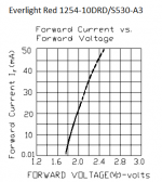
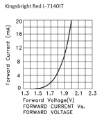
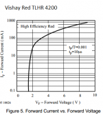
Interesting set of curves. The Kingsbright is much more "horizontal" at the low end, showing more change in Vf for small changes in If. The Vishay is almost vertical through the range we are interested in, almost no change in voltage. I assume there are also temperature effects.
How much did you vary the current to get 0.4V change in the string of 4?
How much did you vary the current to get 0.4V change in the string of 4?
Interesting set of curves. The Kingsbright is much more "horizontal" at the low end, showing more change in Vf for small changes in If. The Vishay is almost vertical through the range we are interested in, almost no change in voltage. I assume there are also temperature effects.
How much did you vary the current to get 0.4V change in the string of 4?
I dont remember exactly cause I stopped when I noticed fairly big differences (in that area) when changing between 1 k and 2k2 resistors with strings and 9 V battery. Then I asked a question (somewhere back) on what current to measure on. Then you answered to do it the better way, with the actual CCSes, which I intend to do when I have the time. Baught a bunch of 9 volters and sockets today for that.
I am combining different 3 mm red led brands that I have to get the combined total. Unfortunately I dont know their brands cause its just leftovers from earlyer projects so I dont know their curves.
Last edited:
The Vishay is almost vertical through the range we are interested in, almost no change in voltage.
That one looks best but some needs some mA to run stable. This one just might since it seems to be able to take alot of current.
I assume there are also temperature effects.
According to the sheet it should be stable up to 60 degrees C
https://www1.elfa.se/data1/wwwroot/assets/datasheets/TLHx42xx_eng_datasheet.pdf
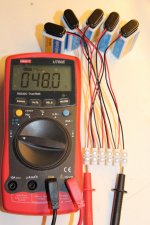
Why you made this octopus power pack?
Mainly to have different voltages for trying out the two CCS-LED strings
True but a couple of tens of a volt is what I got when I varied the current with loadresistors on the strings and for me 0,3-0,4 volts seemed alot for this app. Maybe its not.
Here is Vf/current on 3 common 3mm red leds.
Cool info about leds.... I did not know these could stand such high currents (Vishay)
- Home
- Source & Line
- Analogue Source
- Simplistic NJFET RIAA