Hi Salas
Tech question:
I have some more k369 I would like to use in another of my builds (I have now four folded working builds and all use k170)
I have the following fets:
2 x Idss 11.88
2 x Idss 11.96
Can I mix one 11.88 with one 11.96 in one channel without fearing issues using 3.9ohm for Rs ?
This is because I want to have exactly the same circumstances in both channels and using one pair 11.88 in one channel and 11.96 in the other might get gain differences between channels
tutoring 
The relationship between Id and Vds at a certain Vgs (when in saturation) is a straight line with an upward slope, i.e. Ids slightly increases when increasing Vds. In a common source configuration, higher Vds means lower Id (less voltage drop on Rload), i.e. lower gm. Is this what you refer to?
ouch, my math is quite rusty.... anyhow, this end up in choosing whether it is best to reduce the THD or let it be higher but with a "decreasing" profile of the various products, right?
Thanks!
.....load line cancellation between drain current and drain voltage.......
The relationship between Id and Vds at a certain Vgs (when in saturation) is a straight line with an upward slope, i.e. Ids slightly increases when increasing Vds. In a common source configuration, higher Vds means lower Id (less voltage drop on Rload), i.e. lower gm. Is this what you refer to?
Keep in mind that when cancelling square law devices like tubes and fets the cubic product remains which is the third harmonic. You might want that or not, or to a balance.
ouch, my math is quite rusty.... anyhow, this end up in choosing whether it is best to reduce the THD or let it be higher but with a "decreasing" profile of the various products, right?
Thanks!
If its a triode or a SIC FET then the voltage variable is more effective than when it is a pentode like JFET. Changing Id is the more drastic move in that case.
As the Vds-Id relationships change along a curve there is a portion where the gain tends to be more stable as they mutually start to cancel their influence. There the distortion drops.
Don't go into math, if you got lab gear you try manipulate THD profiles and then you decide by ear.
As the Vds-Id relationships change along a curve there is a portion where the gain tends to be more stable as they mutually start to cancel their influence. There the distortion drops.
Don't go into math, if you got lab gear you try manipulate THD profiles and then you decide by ear.
Hi Salas,
Thank you for corrections.
I would like to buy a kit. What or who is "GB"? Can you please send me a link/contact info.
Sorry for my rank ignorance, but I think that SSLV1.1 shunt is a voltage regulator. Am I right? I use LM317 based voltage reg and it is very noise. I might did not pick right caps (types, value and brands).
I connected my TT to MM input and it is very low gain. With MC it is too High.
What do you thing if I'll change MC Rs to 470R and Rd for 4.7K. My gain should drop roughly to 10dB (from about 30dB, originally set by Rs 50R and Rd 3k16).
Thank you.
Thank you for corrections.
You can get SSLV1.1 regs PCB from the GB that's on now if you want to try shunts.
I would like to buy a kit. What or who is "GB"? Can you please send me a link/contact info.
Sorry for my rank ignorance, but I think that SSLV1.1 shunt is a voltage regulator. Am I right? I use LM317 based voltage reg and it is very noise. I might did not pick right caps (types, value and brands).
The harshness could be due to the heavier than proper interstage loading and extra noise from the gate and source resistors values. IMHO of course. Circuit's internal workings in other words.
You could be over driving it also through the MC stage if you got the 1.58mV cart. Try the straight MM input in that case.
I connected my TT to MM input and it is very low gain. With MC it is too High.
What do you thing if I'll change MC Rs to 470R and Rd for 4.7K. My gain should drop roughly to 10dB (from about 30dB, originally set by Rs 50R and Rd 3k16).
Thank you.
Alexkosha:
-GB is not a person, its a whole section of the forum. Group Buys
-You should query BHL on altering your main section gain to 43dB or something. Its someone's active product and I respect that. I can not be directing unofficial tweaks.
-GB is not a person, its a whole section of the forum. Group Buys
-You should query BHL on altering your main section gain to 43dB or something. Its someone's active product and I respect that. I can not be directing unofficial tweaks.
Hi Salas,
Thank you for directions. I also understand IP concerns.
Theoretically, can my mid-highs harsh sound during high tone be related to capacitors type mix in RIAA?
I use all caps made by Mundorf MPK, but two caps are Russian PIO. I can find Mundorf MKP for 0.034uF. So, I use parallel 0.033uF and 0.0001uF PIO.
Please let me know.
Thank you for advance.
Alex
Hi Salas,
Thank you for directions. I also understand IP concerns.
Theoretically, can my mid-highs harsh sound during high tone be related to capacitors type mix in RIAA?
I use all caps made by Mundorf MPK, but two caps are Russian PIO. I can find Mundorf MKP for 0.034uF. So, I use parallel 0.033uF and 0.0001uF PIO.
Please let me know.
Thank you for advance.
Alex
Oops, I forgot to ask about your opinion of replacement for Russian PIO with Vishay 1837 MKP or other MKPs.
Thank you.
Its RIAA curve is subdued towards the highs by half a dB slant and bumped up in the lows by as much. So I doubt any harshness is related to curve or parts quality issues.
Russian PIO is smooth and somehow dark in general VS MKPs which show more cool detail.
It could be primarily related to its MC input overload with your particular cart. You should ask BHL to advise values for proper gain structure providing them with your cart details.
thank you
Don't worry, its open sounding but smooth as it is calculated and tested. Just follow the guide and it will be alright. Lost or found constants and the like are just arbitrary bits. This one is a fully developed item with a certain rendering that you will subjectively judge as a whole in fitting well or not for your own use.
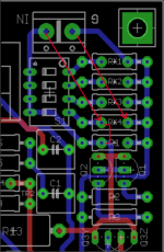
While I appreciate the flexibility offered by the new folded boards, I am not generally one who changes cartridges a lot. My MC cartridge likes a load of about 100 ohms. I am trying to save a little money and minimize component count, so I assume it would be OK to use 100R for R1, and leave out the switch and the Rxn resistors. Is that correct?
- Home
- Source & Line
- Analogue Source
- Simplistic NJFET RIAA

