It was just the BC550 that was the wrong way, the J-fets were ok. ... are these tweaks to the circuit that will improve performance or adjustments that could stop it from working?
If those I noted in your pic clip are the input fets couple leading through 15R common resistor to ground, they are reversed for instance. Make sure. R7 can be more crucial if not 1k5 as suggested but I would expect it to work with 1k still, albeit a bit hot for output fet.
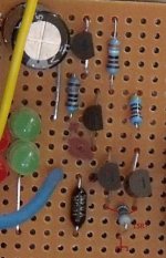
Attachments

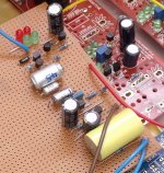
Salas, Thanks very much for your help. I have been using the attached pin-out for the JFets, on my board they all face the same way, and all appear to be correct (as far as I can tell). My supply line is the top-most rail and the ground is nearest the middle of the board. After reversing my BC550 this is what the build looks like:
Attachments
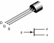
Thanks, I didn't realise that different manufacturers K170's had different pin-outs!
I have reversed all of my JFets and the situation is the same - no humm or buzz or music when I apply a very low-level signal. Could I have damaged the Jfets by installing them the wrong way? What test points can I use in this cct please?
I have reversed all of my JFets and the situation is the same - no humm or buzz or music when I apply a very low-level signal. Could I have damaged the Jfets by installing them the wrong way? What test points can I use in this cct please?
Fortunately, with Gate in the middle and the probable symmetry in the construction, it appears that swapping around a DGS to a SGD does no harm and should perform identically.
However, if what I read is correct then a few are not truly symmetrical (D><S) and you may not be able to tell if they have been swapped for the worse.
However, if what I read is correct then a few are not truly symmetrical (D><S) and you may not be able to tell if they have been swapped for the worse.
What test points can I use in this cct please?
Voltages on all drains and the one BJT collector, referenced to ground. Post those when the circuit runs on 45V supply.
Q2 looks shorted. Either by wrong board connections or burn out. Possible to take Q5 out too by leaving it unbiased lingering at over 40V. What is the voltage across R7? BC550 collector should be ~10V or more. Test that there is no error in the R1, R2, 3.9k and 15R values. Your LEDS must be alight?
Fortunately, with Gate in the middle and the probable symmetry in the construction, it appears that swapping around a DGS to a SGD does no harm and should perform identically.
However, if what I read is correct then a few are not truly symmetrical (D><S) and you may not be able to tell if they have been swapped for the worse.
True, but better we know he has everything in as everybody else that built it before, so to debug without any lingering question marks.
Q2 looks shorted. Either by wrong board connections or burn out. Possible to take Q5 out too by leaving it unbiased lingering at over 40V. What is the voltage across R7? BC550 collector should be ~10V or more. Test that there is no error in the R1, R2, 3.9k and 15R values. Your LEDS must be alight?
Hi Salas, sorry I've been busy for the last couple of weeks.
Collector of BC550 is at 6.3V. the LEDs are alight and measure 7.07V. R7 drops 0.6V. I have checked the resistor values and they are fine.
Edit: I've also replaced all of the Jfets (all of the old ones still measured fine though), the 3.9k and 8.2k resistors were swapped out as my 1W versions have arrived now.
Last edited:
Assuming all connections are done true to the schematic, I would suspect that your two paralleled input fets bias strong and drop too much over R1. What IDSS you used for those? There is 45V PSU when measuring? Do you have a couple ~7mA IDSS ones (using your same method of finding IDSS as your others) to put there and see if the BC550 collector rises enough and there will be output signal? Now the BJT looks cut off. Also up R6 (use a trimmer maybe) until you will see 8-10V across R7.
OK I have replaced the BC550, and replaced the input JFets with two of 7.1mA. BC550 now measures:
c - 12.0v
b - 7.09
e - 6.43
Voltage drops are (45.9V supply):
r1 - 33v
r2 0.09v
r17 - 0.28v
r9 - 0.6v
r10 - 45.1v
r11 - 1.3v
r6 - 0.18v
r7 0.63v
I did find an error, the G of Q2 was connected to the S of Q5, which I've fixed but it doesn't appear have made a difference. The above measurements were taken after this was fixed.
Your first stage looks restored now. Could have been your BC550 because for 7.1mA fets 12V at collector looks normal. Still your second stage should have been showing 8-10V on Q2's drain to earth, biasing the gate of Q5 near there, thus bringing R7 up near 8-10V too. That would make R9 drop about 25V. Still debugging to do on second stage. See if that Q2 gate to Q5 source error had managed some JFET fault on Q2 and/or Q5. Especially exposed to >max voltage is Q5 with that error. Inspect your connections against the schematic very thoroughly around second & third stage once again also.
- Home
- Source & Line
- Analogue Source
- Simplistic NJFET RIAA