hello
i`ve received 2sk170 are but they are GR.i`ve selected them in a few pairs with idss from 3.5ma to 6.2ma.on the schematic of Simplistic RIAA i saw i need BL`s with idss 8-8.5ma.what should i do so i can use three of the pairs of GR`s i have ?
Difficult situation. You have to let us know the cartridge you are having so to estimate the gain needed and maybe give you new resistor values for 3 close pairs you maybe have around a more specific IDSS. Like 5.5-6mA or 4.5-5mA. So state the cartridge and 3 reasonable pairs you can work with.
Sorry I have come in late in this thread. What method did you use to measure Idss. Do you have cct? I have made three Le Pacific style phono preamps in the last four weeks. I'm about to do another and have a bunch of FETs. I would like to match them.i have replaced the pair with high idss 6.24 , 6.17 with another one that has 5.60 , 5.59 ma idss .so i have :
1. 5.53 5.56
2. 5.60 5.59
3. 5.91 5.91
4. 5.93 5.89
i have replaced the pair with biggest idss so i could get the pairs in 5.5-6ma idss range
all you need to match jfets are a multimeter and a 9v battery.more you can find here Transistor matching
What are the dissipations of the two mosFETs during normal operation?
What are the expected Tc & Tj of these mosFETs during normal operation?
What are the dissipations of the mosFETs during worst case fault conditions?
Will the mosFETs survive during fault conditions?
The fact that the second mosFET runs a bit hotter is of virtually no consequence, if you don't know what is happening.
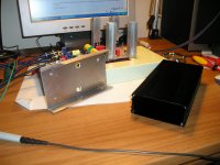
One step before the end. Maybe I have a problem with temperature of second IRFP9240.
Now there is 185 mA for each channel. Can I decrease to 160mA if only change the R1 of PSU from 3.3Ω to 4.7Ω?
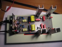
Each phono channel draws around 30mA. If you run at 45V B+ I guess its normal there is considerable dissipation from the shunt Mosfets for those heatsinks in the picture burning the excess. IRFP TO-247s are dogs to say the truth, very reliable, but it will be prudent to lower the CCS a bit to ensure no failures in the long run especially when it will be boxed up.
What are the dissipations of the two mosFETs during normal operation?
What are the expected Tc & Tj of these mosFETs during normal operation?
What are the dissipations of the mosFETs during worst case fault conditions?
Will the mosFETs survive during fault conditions?
The fact that the second mosFET runs a bit hotter is of virtually no consequence, if you don't know what is happening.
Hi AndrewT.
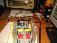
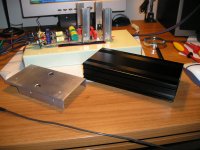
All are working perfect but I am going to use the heatsink and the case you can see on photos. If there is no insufficient cooling may reduce a little the total current per channel.
Attachments
One step before the end. Maybe I have a problem with temperature of second IRFP9240.
Now there is 185 mA for each channel. Can I decrease to 160mA if only change the R1 of PSU from 3.3Ω to 4.7Ω?
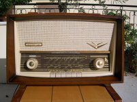
Nice old radio, it's very similar like I heard when I was 4 years old (Telefunken tubed)
")
Hi AndrewT.
All are working perfect but I am going to use the heatsink and the case you can see on photos. If there is no insufficient cooling may reduce a little the total current per channel.
Don't forget to insulate the Mosfets when you will use the case for sinking.
P.S. Auricaps without flying leads? New issue, or suspect?
Nice old radio, it's very similar like I heard when I was 4 years old (Telefunken tubed)
It's my grandfather radio which I have restoration. ERRES KY5953
Attachments
- Home
- Source & Line
- Analogue Source
- Simplistic NJFET RIAA