Hi salas just now i wired MC pre pre. Plugged it into to my phono and all is nice a quiet. some hum but eliminated with positioning of the interconnects away from power leads. The shelter too has arrived. I will install on Saturday can't wait!!
thanks for your nice simple circuit
We discussed two gain settings if I remember well, which one you made as pre-pre? Have a nice weekend playing with new cart.
")
Why would you say that?
The mix Joaquin Rodrigo-Miles "Concierto de Aranjuez" sounds very well
Still mind the same
Nice work !
Please post some pictures of the pcb (after you etch them).
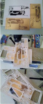
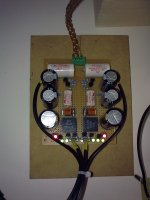
Right now I only have this pictures (from a mobile phone).
First set of pictures, etching and drill.
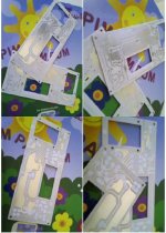
Second set of pictures, silver plating and preparation for varnish.
Output capacitor and FT3 will fit on these square holes
Attachments
Yes, it looks good.
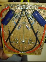
But a comment to the grounding: afaik it is not good to change from wide traces to narrow traces and vice versa.
Specially not when currents are flowing, what is the case for the grounding, specially between the bypass caps.
Franz
/Edit: try to explain (afaik): different size of traces is resulting in minimal differences of conducitvity eg. resistance. When currents are flowing this will produce voltage differences on the grounding traces. And this is to be avoided. Better use one trace width, as large as possible.
Hello Franz
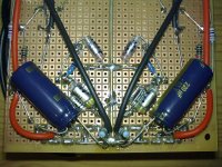
I see what you mean and I believe you are correct, but when I draw this PCB the main goal was to provide a ground plan ( I'm not sure about the english designation) to those big silver mica capacitor's, later on I extended that to other small parts in the PCB.
I don't know wich is better, probably get more damaged than benefits, I don't know.
Next time i will take that on account!
P.S. I only do electronics on a hobby basis, mechanics is my main goal.
We discussed two gain settings if I remember well, which one you made as pre-pre? Have a nice weekend playing with new cart.
Hi Salas i built the Circuit you designed at post 3695 x 10 gain, cartridge op is o.4 mV. I have just fitted the cart. The output is very low just above the background noise with full volume I used a single 9V alkaline, maybe i'll try another battery.
Groovy. Happy end then. The solution was err.. simplistic. If you will never find better pre-pre sound from your input transformers, and gonna keep this active step up, you may need a hefty rechargeable battery or plan to build a good 9V reg for it.
Groovy. Happy end then. The solution was err.. simplistic. If you will never find better pre-pre sound from your input transformers, and gonna keep this active step up, you may need a hefty rechargeable battery or plan to build a good 9V reg for it.
Better a Simplistic Low Voltage Shunt Regulator
Groovy. Happy end then. The solution was err.. simplistic. If you will never find better pre-pre sound from your input transformers, and gonna keep this active step up, you may need a hefty rechargeable battery or plan to build a good 9V reg for it.
That was the album. I was lucky enough to recently get two sealed copies.
Later i will try the mc riaa and its power supply. For now i'll use two batteries dual mono.
That old easy going & groovy family of high musicianship artists with the ultra cool style are to be played on vinyl ONLY. Always bring easy living mood memories.
For now i'll use two batteries dual mono.
My tip:
try a cap in parallel to the battery as nearby to the fet as possible (9V alkaline batteries have a high internal resistance, high output impedance).
Optimal is some foil cap >10uF but you could also use a fine electrolytic with higher capacitance. Or a combination in parallel.
Franz
Last edited:
Hi guys!
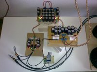
I have been away from this thread for a year or so...but since then I have built the 48dB version of the NJFET RIAA. It's for a complete system I'm building for a friend of mine.
Construction...The coupling capacitors are Mundorf MCap, all resistors are 50ppm/°C metal film (matched to 0.1%) and the RIAA caps are NOS Siemens&Halske styroflex, paralleled with smaller styroflex to get the final capacitances required. I was lucky to have access to a component bridge.
The JFETs are matched L/R and all within together 0.2mAvor so. The input JFETs were measured at three different currents to match them for linearity as good as possible.
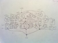
From the schematic I drew a layout for P2P and started soldering. I employed a mixture of star grounding and ground-follows-signal, with the input being the central ground point. The whole board (stereo) measures 10x8 cm.
For the bootstrapping I used a BC547C, currently operating with 7.96V/7.93V base voltage (L/R). The supply voltage is 27.20V/27.20V.
System...The output high-pass (3u3 and 1M) is designed to have -3dB@12Hz when it sees a 25k load. I run the RIAA into a B1 with a 25k pot at the input. The main amp is a Mini Aleph working into FE108ESigma horns. The TT is the only non-DIY piece of equipment. It's a Pro-ject RPM1 with a vintage (read: older than me) Shure M75 from my mom's old TT.
Noise...With no record playing and the volume all the way up (mind you, it's a B1) I can hear some noise and hum from the speakers, which is most probably picked due to the open design. At normal listening levels I have to put my ear right next to the speaker to hear it.
Sound...Well, what can I say, it's the first time I'm listening to vinyl outside of a club, and compared to any digital equipment I have heard so far, it's just lovely. It flows, it's just right there. I account a big part of that to Salas' RIAA.
That's about it, many thanks to all you guys for developing and pushing this design!
Dave
I have been away from this thread for a year or so...but since then I have built the 48dB version of the NJFET RIAA. It's for a complete system I'm building for a friend of mine.
Construction...The coupling capacitors are Mundorf MCap, all resistors are 50ppm/°C metal film (matched to 0.1%) and the RIAA caps are NOS Siemens&Halske styroflex, paralleled with smaller styroflex to get the final capacitances required. I was lucky to have access to a component bridge.
The JFETs are matched L/R and all within together 0.2mAvor so. The input JFETs were measured at three different currents to match them for linearity as good as possible.
From the schematic I drew a layout for P2P and started soldering. I employed a mixture of star grounding and ground-follows-signal, with the input being the central ground point. The whole board (stereo) measures 10x8 cm.
For the bootstrapping I used a BC547C, currently operating with 7.96V/7.93V base voltage (L/R). The supply voltage is 27.20V/27.20V.
System...The output high-pass (3u3 and 1M) is designed to have -3dB@12Hz when it sees a 25k load. I run the RIAA into a B1 with a 25k pot at the input. The main amp is a Mini Aleph working into FE108ESigma horns. The TT is the only non-DIY piece of equipment. It's a Pro-ject RPM1 with a vintage (read: older than me) Shure M75 from my mom's old TT.
Noise...With no record playing and the volume all the way up (mind you, it's a B1) I can hear some noise and hum from the speakers, which is most probably picked due to the open design. At normal listening levels I have to put my ear right next to the speaker to hear it.
Sound...Well, what can I say, it's the first time I'm listening to vinyl outside of a club, and compared to any digital equipment I have heard so far, it's just lovely. It flows, it's just right there. I account a big part of that to Salas' RIAA.
That's about it, many thanks to all you guys for developing and pushing this design!
Dave
Attachments
You watch football and blow vuvuzelas, I experiment on phono.
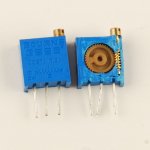
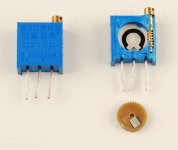
Hi Salas,
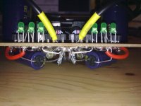
I see you're using multiturn pots in you design. Here's how they look inside.
Personally, i don't like them (they sometimes creep). But honestly, I love the vuvuzelas, from a distance at least...
Attachments
Hey, thats nice DIY! Congratulations. It certainly needs a box to be sure about hum residual isn't field pick up or needs some grounding tweak. Multiturn trimmers are mainly problematic when there is some appreciable power on their wiper, its good to sub them with resistors after finding the best value for bias by watching THD in experimental builds.
P.S. Since you got your 47k cart load resistors on mini sockets, try 68k and 100k also for your Shure, maybe there will be a finer combination or not. Its easy to test.
P.S. Since you got your 47k cart load resistors on mini sockets, try 68k and 100k also for your Shure, maybe there will be a finer combination or not. Its easy to test.
Shure M75 from my mom's old TT.
As I wrote earlier: it is an often underestimated cartridge! Swiss public broadcast used this cartridges on their EMT's!
Just try the correct capacitive load together with your phono cables!
Something between 200 to 600pF in parallel to the input resistor and you can find the point where it begins to sing.
Correct mounting of the cartridge and adjustement of the tonearme are essentially, before testing the needed capacitive load.
Franz
/Edit: best caps for this task, imho: Styroflex.
Last edited:
It doesn't mean anything.As I wrote earlier: it is an often underestimated cartridge! Swiss public broadcast used this cartridges on their EMT's!

Radio Vaticana (the Pope's radio!) known in Italy for very high quality classical music programs used to install on their several EMTs only cheap Stanton 500s. I used to sell them dozens.
Do you know why? 'Cause they where the cheapest avaliable!
- Home
- Source & Line
- Analogue Source
- Simplistic NJFET RIAA