Salas
I forgot to change the value of R1/R101 in the drawing, but I have prepared two 2k2 resistors.
And in my circuit, board, I have the resistors C9a/C9b to stabilize the first stage.
Juma
Of course, I did knew, that LM317 can be used for higher voltages, also for tube amplifier supplies. It is the max input/output difference limiting their use.
But: it will be more noisyer due to the zener or diode.
Franz
Last edited:
Hello
This is my first post and first of all I would like to give my congratulations to all the people who contribute to this wonderful forum, and a special congratulation to Salas on this thread.
Well I decided to build one of this phono pre amplifier, it's s for a Audo Technica AT31E, so I pick up all the components and design a new PCB according thread info.
Yesterday I decided to etch my PCB'S but first I decided to check the forum for some news concerning this project, and I realized there is some modifications, so i have some questions.
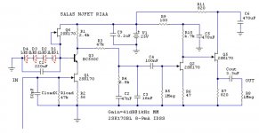
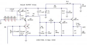
My schematic is K170BL IDSS8-9mA Gain 56db MC.
- I want to use paralleled Q1 with also a paralled R2, should I use 33R on this ?
- I gonna change the position on schematic for C1, so I need to use R17, but, how about R1-6,2K and R3-43K, should I keep that values ?
- What is the correct value for RloadX, 1K on the schematic , right now I see some schematics with 150R.
- And last one, how about R6-27R, should I change it to a trim pot ?
These ones are not finished yet, but I will post the new ones ASAP.
This is my first post and first of all I would like to give my congratulations to all the people who contribute to this wonderful forum, and a special congratulation to Salas on this thread.
Well I decided to build one of this phono pre amplifier, it's s for a Audo Technica AT31E, so I pick up all the components and design a new PCB according thread info.
Yesterday I decided to etch my PCB'S but first I decided to check the forum for some news concerning this project, and I realized there is some modifications, so i have some questions.
My schematic is K170BL IDSS8-9mA Gain 56db MC.
- I want to use paralleled Q1 with also a paralled R2, should I use 33R on this ?
- I gonna change the position on schematic for C1, so I need to use R17, but, how about R1-6,2K and R3-43K, should I keep that values ?
- What is the correct value for RloadX, 1K on the schematic , right now I see some schematics with 150R.
- And last one, how about R6-27R, should I change it to a trim pot ?
These ones are not finished yet, but I will post the new ones ASAP.
Attachments
Hello
This is my first post and first of all I would like to give my congratulations to all the people who contribute to this wonderful forum, and a special congratulation to Salas on this thread.
Well I decided to build one of this phono pre amplifier, it's s for a Audo Technica AT31E, so I pick up all the components and design a new PCB according thread info.
Yesterday I decided to etch my PCB'S but first I decided to check the forum for some news concerning this project, and I realized there is some modifications, so i have some questions.
My schematic is K170BL IDSS8-9mA Gain 56db MC.
- I want to use paralleled Q1 with also a paralled R2, should I use 33R on this ?
- I gonna change the position on schematic for C1, so I need to use R17, but, how about R1-6,2K and R3-43K, should I keep that values ?
- What is the correct value for RloadX, 1K on the schematic , right now I see some schematics with 150R.
- And last one, how about R6-27R, should I change it to a trim pot ?
These ones are not finished yet, but I will post the new ones ASAP.
Those are not modifications exactly, those are tweaks so to get a 60dB circuit for low MC at same noise level as the 57dB.
Your cart is 0.4mV and the 57dB you draw will serve it rightly.
Leave R6 as it is, make R7 1k2 instead of 1k. Use 100R trimmer for R2 instead, so you can match the two channels for 10V at Q3's collector.
RloadX is only a general value when we don't know the specific cart that will be used. Those 150R were recommended since people who asked for LowMC had the Denon DL103R. Yours looks like will be happy with 100-150R. But this is something you got to listen for, maybe you can install pins for exchanging that resistor easily on tests.
Changing the BC550 base decoupling tied to B+ is an option said to improve PSRR. Regulating the LEDs current lower with a 100Rs is good for the Q6 JFET's dissipation.
R1 & R3 you must not change, they are crucial values for the Riaa filter.
Salas
And in my circuit, board, I have the resistors C9a/C9b to stabilize the first stage.
Franz
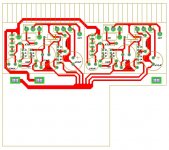
Yes, but I see it wired before all other RC, when to decouple 1st stage from the others it would need to serve only stage 1 as I have shown in that little example I cropped and attached. I stopped using that when with V1.2 Reg so not to impose the electrolytic ''signature'' but it really depends on how the remote is wired in relation to first stage, and in your case it maybe better to have. You can always listen with or without that RC and decide. I don't know with that circle GND trace or local stars connected to a main star, I would thought it will be easier to debug hum issues if having stage sub stars. If we see yours as a bus bar, then it will be better to ground on input resistor's ground side.
Salas
I will keep it in my mind, should I need to debug hum or worse, motorboating.
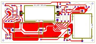
Just edged the board, low quality
The toner transfer method does not always work as expected, but I will go now...
BTW: there is no (closed) circle ground! It is carefully separated between input, output and psu. And yes, the star point. But it will be easy to separate grounds of both channels when needed.
Franz
I will keep it in my mind, should I need to debug hum or worse, motorboating.
An externally hosted image should be here but it was not working when we last tested it.
Just edged the board, low quality
The toner transfer method does not always work as expected, but I will go now...
BTW: there is no (closed) circle ground! It is carefully separated between input, output and psu. And yes, the star point. But it will be easy to separate grounds of both channels when needed.
Franz
Last edited:
Yes, but I see it wired before all other RC,
Ahhh, yes, I have overseen R18 in your circuit.
I will look if I can apply a fix for this pcb or edge another one...
Franz
/Edit
there are still R9 and R11 decoupling following stages from the first one!
Last edited:
Yes, that is why I generally skip it when using very low output impedance regs, especially when double mono. Its what it does with the other channel's 1st stage if there is just one reg that RC may prove helpful or not. But you can easily mod it receives from a central B+ node even as it is etched I guess with a knife and a jumper. There is space to move R12 next to R3, jumper the now R12, and cut the now 1st stage branch from the B+ distribution node.
There is space to move R12 next to R3, jumper the now R12, and cut the now 1st stage branch from the B+ distribution node.
Yes, I have also seen this possibility to modify this board.
I will write about the results.
Franz
Thanks SalasThose are not modifications exactly, those are tweaks so to get a 60dB circuit for low MC at same noise level as the 57dB.
Your cart is 0.4mV and the 57dB you draw will serve it rightly.
Leave R6 as it is, make R7 1k2 instead of 1k. Use 100R trimmer for R2 instead, so you can match the two channels for 10V at Q3's collector.
RloadX is only a general value when we don't know the specific cart that will be used. Those 150R were recommended since people who asked for LowMC had the Denon DL103R. Yours looks like will be happy with 100-150R. But this is something you got to listen for, maybe you can install pins for exchanging that resistor easily on tests.
Changing the BC550 base decoupling tied to B+ is an option said to improve PSRR. Regulating the LEDs current lower with a 100Rs is good for the Q6 JFET's dissipation.
R1 & R3 you must not change, they are crucial values for the Riaa filter.
Let see if I get it right
Attachments

Delete the horizontal line from node R17 to Q6's gate. 220uF capacitor's + goes to B+ 37V is the correct polarity of course. The 50pF input load capacitor is not needed. Delete its position or leave it blank for your AT31E that states 100-200pF, so much comes from the TT cable. About double JFET I will check and let you know if it can work with those values around it with proper gain etc.
P.S. I checked it out. Delete the paralleled 2nd JFET in first stage. It will up the trimmer setting adding noise, that will about offset its benefit, plus it will make it lose some gain since it will alter the Vgs point.
P.S. I checked it out. Delete the paralleled 2nd JFET in first stage. It will up the trimmer setting adding noise, that will about offset its benefit, plus it will make it lose some gain since it will alter the Vgs point.
Delete the horizontal line from node R17 to Q6's gate. 220uF capacitor's + goes to B+ 37V is the correct polarity of course. The 50pF input load capacitor is not needed. Delete its position or leave it blank for your AT31E that states 100-200pF, so much comes from the TT cable. About double JFET I will check and let you know if it can work with those values around it with proper gain etc.
P.S. I checked it out. Delete the paralleled 2nd JFET in first stage. It will up the trimmer setting adding noise, that will about offset its benefit, plus it will make it lose some gain since it will alter the Vgs point.
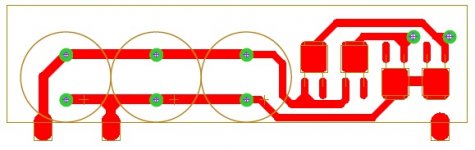
OK, one last question , how about this configuration ( someone on a previous post did it), some benefit or should I stay with only one.
If affirmative I will replace R2 by a trim pot.
Attachments
I don't love the idea, but for sure I appreciate your comments.
Final drawing will be with only one Q1, R2-33R and I will do the tweak on C1, rest of values as you mention on previous post.
I will post my PCB'S (for dual power supply and pre).
Hope I can finish that today
P.S. The program I'm using can convert this drawings to gerber and excellon formats. I can post them also but I'm not shure if they are correct.
what about during start up? Particularly if there is a discharged capacitor on the output.
Is there any data for the 317 subjected to transient voltage overload?
I cannot see the transient voltage overload data.It's always beneficial to carefully read the datasheet ...
- Home
- Source & Line
- Analogue Source
- Simplistic NJFET RIAA