I changed & the Right channel don't sound, I changed to reverse & both channels sound. 2nd time changed again & right channel don't sound, reversed & both channels sound. 3rd time connected left to left & right to right & both sounds finally ok. Seems like inside the phono RIAA the connections are reversed, I will open to be sure & will change the cables for coaxials as kind advice of Salas.:
Maybe you got some reversed connection on your board sockets on the twisted audio runs or where it continues on your board layout, so reverse works. After you will solve your issues one by one for hum, and you will have double mono regs remote sensed, expect much more in the way of detail and dynamics. Also if you got a test record, we will fix the channels level matching, including cart. Its easy.
Congratulations on your debugging progress so far.
Thanks, tonight listened a lot with coaxial RG174 teflon with copper silver plated cables, less hum, still something that suppose will avoid with R-Core Tx but now is possible enjoy the music.
Next week I will buy the RG-58 for remote sensing, also I have in mind a copper foil to shield inside chassis connected to:
1-GND PCB RIAA
2-Chassis to the same GDN that cables TT
Wich of both will shield better, or there is other better?
Other possibility is a Permalloy foil instead the copper foil & ESR tape over the permalloy or copper foil.
Any suggestions?
Could you suggest the test record to adjust the levels & where to buy?
Last edited:
The rest of your hum is ground loops, since you have the transformer in a different remote box. After you will get both transformers (R-core in single box I suppose?) we can review your final ground scheme. Meanwhile, is your hum objectionably much, in the way you firstly set it? Can I see a picture birds eye view with the coaxial signal cables installed, and another one of your psu box? Maybe we can see something to wire differently for now.
Look for HFN&RR test record by googling.
Look for HFN&RR test record by googling.
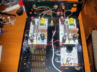
The photo with coax cables inside & the C5 changed in the reg.
Follows the channel changed
An externally hosted image should be here but it was not working when we last tested it.
Follows the channel changed
The PS photo:
An externally hosted image should be here but it was not working when we last tested it.
Try one ground cable to the chassis in nearest easy point for a screw from central gnd out of the shunt like in the edited photo. Also 10nF caps directly from each input RCA gnd ring (with short leg to the ring) to nearest point on chassis.
What is that cable I point with question mark? Is it for TT ground lug, and is it going one time locally to chassis and it goes again to the green chassis-chassis-mains ground? Or is it going to psu 0? Cut it out, make the TT ground lug in touch with chassis if it does not now. Shorten and twist the white AC cables in the PSU box, get em away from the DC part on the left. See if its any better, let me know. Also can I see the Linn with the cart on arm angle shot?
What is that cable I point with question mark? Is it for TT ground lug, and is it going one time locally to chassis and it goes again to the green chassis-chassis-mains ground? Or is it going to psu 0? Cut it out, make the TT ground lug in touch with chassis if it does not now. Shorten and twist the white AC cables in the PSU box, get em away from the DC part on the left. See if its any better, let me know. Also can I see the Linn with the cart on arm angle shot?
Attachments
Try one ground cable to the chassis in nearest easy point for a screw from central gnd out of the shunt like in the edited photo. Also 10nF caps directly from each input RCA gnd ring (with short leg to the ring) to nearest point on chassis.
What is that cable I point with question mark? Is it for TT ground lug, and is it going one time locally to chassis and it goes again to the green chassis-chassis-mains ground? Or is it going to psu 0? Cut it out, make the TT ground lug in touch with chassis if it does not now. Shorten and twist the white AC cables in the PSU box, get em away from the DC part on the left. See if its any better, let me know. Also can I see the Linn with the cart on arm angle shot?
Try one ground cable to the chassis in nearest easy point for a screw from central gnd out of the shunt like in the edited photo ok I will do
Also 10nF caps directly from each input RCA gnd ring (with short leg to the ring) to nearest point on chassisso I have to connect input RCA gnd to chassis with a 10nF cap?
What is that cable I point with question mark? Is it for TT ground lug, and is it going one time locally to chassis and it goes again to the green chassis-chassis-mains ground? Or is it going to psu 0? is going to PSU 0
Shorten and twist the white AC cables in the PSU box, get em away from the DC part on the left ok I will do
Photo TT gnd inside chassis:
An externally hosted image should be here but it was not working when we last tested it.
Photo TT gnd outside chassis:
An externally hosted image should be here but it was not working when we last tested it.
The five pins connector (right up silver colour) is PS.
Wich test record is:


Also can I see the Linn with the cart on arm angle shot?this photo serve you?
An externally hosted image should be here but it was not working when we last tested it.
Yes that is the test record.
Yes put 10nF cap from each input RCA ground ring directly and nearest to chassis. Grounds RF right away. Clears the signal audibly in my tests with this phono with low MC.
Disconnected TT ground lug from psu 0. Leave it clean only to chassis as you did on the photo above. Will see ground again, bcs a new cable will connect shunt's 0 to chassis.
I see you use a bit forward VTA tilt for DL103R. That works good for me. Is that an Ekos?
Lets see if you get any better hum and stronger signal.
Thks I will buy the test record.
I never connected the TT ground lug to PSU 0. The ground TT loug is connected only to chassis. I will connect a new cable from shunts 0 to chassis.
I have problems with the setup between Ekos & DL-103R, the cart is not enough high & the cartridge clips needs more space, seems like the cart needs another arm more long. About VTA yo know: forward VTA more precise and analytic sound, less forward more warm sound, like general rule but every LP is a world, as always we can take a compromise or you become full changing every LP the VTA.
Now I will finish all advices & I will let you know.
vgeorge, yes that's was mine 1st idea waht I don't have room to rotate the boards 180º, you're right the Salas photo show the 10nF caps at the output.
Salas the 10nF caps are in the input right?
Yes to the input I want them. Got it sketched fast, must have been carried away by the general practice that shorter cables face input of boards.
vgeorge, ok now I understand I will rotate.
Salas, amazing NO HUM:
Salas, amazing NO HUM:
An externally hosted image should be here but it was not working when we last tested it.
An externally hosted image should be here but it was not working when we last tested it.
I only hear one song, in this moment I am watching TV: F.C. Barcelona versus Valencia football match, Barça wins 1-0.
He, he, southern comfort.
- Home
- Source & Line
- Analogue Source
- Simplistic NJFET RIAA