Konnichiwa,
Don't worry about it.
I used 1:20 stepup, 47K on secondary....
Depends, but usually no.
Sayonara
fred76 said:in my particular phonostage, the MC output signal would also pass through the MM stage’s 100pF input cap
Don't worry about it.
fred76 said:What Rload/s do you recommend for the 103R when used with step-up trannies??
I used 1:20 stepup, 47K on secondary....
fred76 said:Does this also hold true for coupling caps in phono sections not just decouplers?
Depends, but usually no.
Sayonara
Konnichiwa,
Sure. In that case this thread might help:
http://www.diyaudio.com/forums/showthread.php?postid=942381#post942381
Sayonara
arnoldc said:Possible to use the MC front-end with your Tubed el cheapo phono?
Sure. In that case this thread might help:
http://www.diyaudio.com/forums/showthread.php?postid=942381#post942381
Sayonara
I used 1:20 stepup, 47K on secondary....
Thanks. So the net load the 103R would 'see' is ~61 Ohms for a 51k1 MM input.
regards,
fred
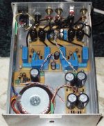
Do you feel that the 1 u decoupling Wimas are enough for the 637 in this circuit ? Could the "blue" MKP Siemens bricks used instead ?
Hi Marinos,
Only used those blue siemens mkp for coupling. They are quite good sounding for the money, just a bit larger than most mks/mkt caps of the same value/vdc rating.
Attachments
Konnichiwa,
For my original 47K Input and a 1:20 stepup the effective load (accounting fro winding resistance etc.) would come to 120R.
(47000 / (20*20) = 117.5)
Sayonara
fred76 said:
Thanks. So the net load the 103R would 'see' is ~61 Ohms for a 51k1 MM input.
For my original 47K Input and a 1:20 stepup the effective load (accounting fro winding resistance etc.) would come to 120R.
(47000 / (20*20) = 117.5)
Sayonara
Moin T,
in Audiophile n°5, june 1978 Jean Hiraga published this circuit. So all credits should be adressed to him.
LG Carsten
PS: if anybody is interested in scans, feel free to email me.
Kuei Yang Wang said:Others have mentioned the "single gemstone headamp", which originiating the japano-french envoironment of Kaneta, l'Audiophile and co is seriously good.
in Audiophile n°5, june 1978 Jean Hiraga published this circuit. So all credits should be adressed to him.
LG Carsten
PS: if anybody is interested in scans, feel free to email me.
Konnichiwa,
I have seen similar circuits in MJ, I'd be hard pressed to be certain if there was a publication pre 78 in MJ or not, however it is a fairly common circuit. I have seen it ascribed to kaneta (Kaneda) as well. However the popularisation in Europe is certainly due to Jean Hiraga.
Sayonara
carawu said:in Audiophile n°5, june 1978 Jean Hiraga published this circuit. So all credits should be adressed to him.
I have seen similar circuits in MJ, I'd be hard pressed to be certain if there was a publication pre 78 in MJ or not, however it is a fairly common circuit. I have seen it ascribed to kaneta (Kaneda) as well. However the popularisation in Europe is certainly due to Jean Hiraga.
Sayonara
My next stop was to seek to remove the need for biased, back to back electrolytic capacitors in the output coupling circuit (4). I instead provide around +0.5V Bias on the OPA637 Output by adding a 1.5MOhm resistor from the positive supply line to the Offset nulling input pin 1. This use is specific to using the OPA637 or OPA627.
If I were to omit the 1.5Mohm resistor for use with other single opamps such as the AD8610 or dual opamps lacking an offset trim pin, how would this affect operation of the circuit? I'm sort of a newbie and don't know what the 0.5V bias is needed for.
Konnichiwa,
Not very much. You would only loose the definite polarisation of the Op-Amp output.
It is needed to bias the output coupling capacitor, see the Jung/March article referenced earlier.
Sayonara
gnuZ said:If I were to omit the 1.5Mohm resistor for use with other single opamps such as the AD8610 or dual opamps lacking an offset trim pin, how would this affect operation of the circuit?
Not very much. You would only loose the definite polarisation of the Op-Amp output.
gnuZ said:I'm sort of a newbie and don't know what the 0.5V bias is needed for.
It is needed to bias the output coupling capacitor, see the Jung/March article referenced earlier.
Sayonara
Kuei Yang Wang said:Konnichiwa,
For my original 47K Input and a 1:20 stepup the effective load (accounting fro winding resistance etc.) would come to 120R.
(47000 / (20*20) = 117.5)
Sayonara
I see, so you just used the 'natural resistance'... I first thought that you terminated 47k R's at the secondaries so that it would be in || with the 47k MM input. Thanks.
regards,
fred
analoug addicts phono pcb
Dear ALL, has any one got a PCB layout for thornstens Analoug phono amp, so that i may attempt to have a go, or would it be ok on vero board (bare with me on this one boys!- i am a newbee!)
thanks all you kind hearted, generious spirited people out there: :
johnny
ps why aint there a spell checker on this!!!!
Re: analoug addicts phono pcb
Konnichiwa,
Veroboard is fine, try using stuff without copper, consider using two sheets "stacked" for more rigidity and solder directly using the component wires in most cases, it actually sounds better that way.
Sayonara
Konnichiwa,
johnny555 said:Dear ALL, has any one got a PCB layout for thornstens Analoug phono amp, so that i may attempt to have a go, or would it be ok on vero board
Veroboard is fine, try using stuff without copper, consider using two sheets "stacked" for more rigidity and solder directly using the component wires in most cases, it actually sounds better that way.
Sayonara
pcb
...or check out this thread...
http://www.diyaudio.com/forums/showthread.php?s=&threadid=71839&highlight=
Read it carefully, because there are lot of interesting suggestions there, including making the whole thing ¨dead bug style¨ over a solid piece of copper -and using that copper as ground- .
Enjoy
Re: phono stage pcb
Konnichiwa,
First, most if not all of the Info for the old and new cheapo apply equally, there are small differences, but nothing really worrisome.
Past that, yes, i have job as well... ;-)
Sayonara
Konnichiwa,
johnny555 said:Thank you for your reply gents, ill tell you what i do when i degest the info, thanks again (very quick-do you have jobs?)
First, most if not all of the Info for the old and new cheapo apply equally, there are small differences, but nothing really worrisome.
Past that, yes, i have job as well... ;-)
Sayonara
I will second Johnny on that one. It would give the chance to build this circuit, to a lot more people. Not everybody wants to venture into the P2P world. Granted, a pcb makes it a lot easieranaloug addicts phono pcb
")
I would welcome it, if someone would post a few useful PDF's, so everyone could etch a couple of boards. With the funky reviews about this phono-preamps sound quality, I think it deserves a larger audience
Steen
steenoe said:
I will second Johnny on that one. It would give the chance to build this circuit, to a lot more people. Not everybody wants to venture into the P2P world. Granted, a pcb makes it a lot easier
I would welcome it, if someone would post a few useful PDF's, so everyone could etch a couple of boards. With the funky reviews about this phono-preamps sound quality, I think it deserves a larger audience
Steen
Here's a compact (2.9" x 1.2") PCB I made after reading this thread. I really like small, tight layouts so I decided to go with 1% Panasonic ERO-S2 metal film resistors and Panasonic ECQP(Z) polypropylene capacitors. The RIAA caps are available in 1% tolerance (except the 330pF cap which is only available in 5% I believe). All parts (except the 0.22uF output cap) have 0.2" lead/grid spacing. As you can see some polypropylene caps appear to overlap some resistors, this is because they don't sit flush with the PCB (or at least, I think they don't). Also all of these parts are available from DigiKey, minus the BlackGate caps.
The CCS resistors have been omitted and should be attached to the underside of the board if needed. The 1.5Mohm bias resistor has been omitted since this layout revolves around a dual opamp.
Input, output and power grounds have been kept separate for an ideal star ground implementation. Grounds can be connected together using hook-up wire on the underside of the board only if absolutely necessary, but will probably result in ground loops.
I encourage anyone and everyone to take this layout and do what you want with it. I'll be posting the black and white outlines in a moment. Feedback is encouraged.
Attachments
- Status
- This old topic is closed. If you want to reopen this topic, contact a moderator using the "Report Post" button.
- Home
- Source & Line
- Analog Line Level
- The Analogue Addicts Phono Preamplifier 2006 Edition