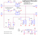
Thanks Geoff, here is a circuit you can follow, it's the production version MkII, and also the purist version, the supply shown is just as good as pure battery power, so no need to good any more exotic with it.
And if you want, you use two single 100k log pots instead of a dual, then that way you have balance (dual mono) for awkward shaped rooms or unbalanced systems.
Cheers George
And if you want, you use two single 100k log pots instead of a dual, then that way you have balance (dual mono) for awkward shaped rooms or unbalanced systems.
Cheers George
Attachments
George, many thanks for the circuit. I will build two separate mono units, since they will be located each on their own loudspeaker. This means that I am not too worried about matching!
I'm now thinking about a similar solution to the selector switch problem - do you have any experience? (I've been unable to play anything but vinyl since soldering in my source to get the sound quality - a shame since I have a Nak tape deck and a Leak tuner standing dumb!)
Best regards
I'm now thinking about a similar solution to the selector switch problem - do you have any experience? (I've been unable to play anything but vinyl since soldering in my source to get the sound quality - a shame since I have a Nak tape deck and a Leak tuner standing dumb!)
Best regards
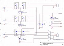
Here is one I have on file, 3 inputs, but it needs a few ldr's, but not impossible.
You guys also will be happy to know that the Lightspeed Attenuator has made Class B in preamps again in Stereophile Recommended Components, it got 5 star value as well because most of Class B is $3K +.
An email to me said it would never get to Class A because of it's $470 price, how's that for $'s count in what placement you get.
Cheers George
Attachments
Hi Andrew, yeah simple in theory, and automatically shorts out the two unused inputs, but what a nightmare to match up the 14 ldr's for stereo use, wouldn't wish it on my worse enemy. Why can't somebody make the perfectly consistent ldr's. Suppose then I'd be out of business.
Cheers George
Cheers George
why 2 series ldrs?
George,
A quick question: why are 2 series LDRs needed with the muting relay? I'd think you could just put the relay to gnd after or before the (one) series LDR.
Hi Andrew, yeah simple in theory, and automatically shorts out the two unused inputs, but what a nightmare to match up the 14 ldr's for stereo use, wouldn't wish it on my worse enemy. Why can't somebody make the perfectly consistent ldr's. Suppose then I'd be out of business.
Cheers George
George,
A quick question: why are 2 series LDRs needed with the muting relay? I'd think you could just put the relay to gnd after or before the (one) series LDR.
it would be nice if you mention that the original idea came from here: www.audiofaidate.org - lightspeed attenuator+progetto HiFun controllo preHere is one I have on file, 3 inputs, but it needs a few ldr's, but not impossible.
")
Attachments
Last edited:
Which icon should I toggle to see an english translation?it would be nice if you mention that the original idea came from here:
italian only, sorry.Which icon should I toggle to see an english translation?
You can try with Google Translate or Babelfish: Translation result for http://www.audiofaidate.org/forum/viewtopic.php?f=1&t=2576
Will the real Velocità della luce please stand up.
It is too bad a lot of credit is not given where it is due.
Wonder what the patent office would say - if you know what I mean.
it would be nice if you mention that the original idea came from here: www.audiofaidate.org - lightspeed attenuator+progetto HiFun controllo pre
It is too bad a lot of credit is not given where it is due.
Wonder what the patent office would say - if you know what I mean.
well, although nowadays we see patent claims for just about anything, even hot water, I don't think there's anything really patentable on this subject. Use of LDRs as analog attenuators and/or audio switches is a pretty old idea...Wonder what the patent office would say - if you know what I mean.
(I bet there may be already some patents on the subject, perhaps 50 years old or more).
Hi Andrew, yeah simple in theory, and automatically shorts out the two unused inputs, but what a nightmare to match up the 14 ldr's for stereo use, wouldn't wish it on my worse enemy. Why can't somebody make the perfectly consistent ldr's. Suppose then I'd be out of business.
Cheers George
I built one recently that has 4 sources to select from and one set of outputs. No matching necessary. The setup is like in the schematic you showed George. I suppose general matching is necessary to make sure you dont get a bum LDR. But I just match at one point around 250R to make sure they are in general vicinity of each other. Then transistors turn them ON/OFF and if I use a trimmer with power to wiper of trimmer then from A and B of trimmer to the base of transistors .... I can balance the LDRs out til they match. I use an optocoupler to ground. Not an LDR but basically a transistor to ground between the two LDRs. It works great on the bench but right now I am getting about 600R in series. I need to tweak the value of the resistor that is in series with A or B to the transistor base and I will get the 40R or so that I am looking for. I think it will work very well. Jon Ver Halen gave me the idea a year and half or two back. I need to remember to send him a board when I get it finalized.
I recently have been listening to an input switcher by John Chapman of Bent Audio. It uses relays. Fantastic sound! Holy Smokes! Way better than others I have listened to like those red boards/blue relays on Ebay. Dont know what is so special about the relays he uses but hoping that I can get even better results with this little setup.
So guys, you can simply use a few pots to balance out your two channels if you want to use LDRs for input switching. Very possible. However, George is right.. You dont want to use just one LDR per channel. You must use two and the relay or however you send signal to ground must be between the two LDRs or else you will short a preamp to ground or you will mute your amp when you try to select another input. The dual LDR solution isolates the amp from any other sources and keeps a huge amount of resistance on either side of whatever solution you use to ground which also keeps your source from shorting to ground. Probably your source would be okay shorted to ground if its output is a decent opamp as they are often rated for continuous short but you cant count on it.
Another solution I have been thinking is like this..
A source sends signal and the LDR is ON so signal (this is with just one LDR) passes to the amp. When we want to turn that source off the LDR goes dark and the signal has the opportunity to pass through a 50R, or so, resistor to a relay to ground. We get rid of the cost of one LDR and the regular resistor is only in the signal when the relay is ON which is when you dont want to listen to that source anyway. This way does not 100% attenuate the signal but man it wont be something you will hear. When the signal has a chance to go through 50R to ground or 20MegOhms.... how much do you think is passing to the amp?! Still, dual LDR is probably best solution. I need to get in the workshop and get my series resistance down to 80R, then I will be happy
Glad to see some activity on the thread again. Hope you are all doing well.
If anyone is going to make it to LoneStar Audio Fest this year in Dallas TX please let me know. Would love to make your acquaintance.
Uriah
it would be nice if you mention that the original idea came from here: www.audiofaidate.org - lightspeed attenuator+progetto HiFun controllo pre
I dont think George was claiming invention of that circuit. If I recall I think someone posted that on THIS THREAD years ago. Could even be your Italian dude. George was nice enough to recall it for us.
Silonex shows similar solutions.
Uriah
yes, in fact.I dont think George was claiming invention of that circuit. If I recall I think someone posted that on THIS THREAD years ago. Could even be your Italian dude.
Unfortunately that project was never completed.
I dont think George was claiming invention of that circuit. If I recall I think someone posted that on THIS THREAD years ago. Could even be your Italian dude. George was nice enough to recall it for us.
Silonex shows similar solutions.
Uriah
Yes like I said I had it on file, and never claimed it to be mine, along with heaps of other Lightspeed circuits, some good some bad, I had no rememberance of who sent it and when. I have never built it, but like I said if your up to the matching go ahead.
Cheers George
Does this mean:
Pete, this is what Pete Daniel sent me on the LM3875.
Quote>Hi,
I'm using minimized configuration with 22k feedback resistor. The input
impedance will influence the DC offset. Anything higher than 22k is not
recommended as the offset increases. With 50k you may get 200mV or so,
depending on chip.
The input shunt resistor in my amps (kits) is 22k so it takes care if you
use higher value potentiometer. 50k is still fine, as the combined shunt
impedance will never be higher than 22k.
Peter< Quote
So from that I say you can change the input resistor to say 200k but always have the Lightspeed attached and powered, before turning the amps on, this should keep the dc offset low.
Also I would keep the interconects to a minimum length with good sheilding.
Then I would work on getting the ouput impedence of your source (CD player) down to below 50ohms with a good strong opamp 50mA or so (I like the AD825 for this).
Cheers George
..that if I use the LDR as a volumecontrol for the B1 buffer, things will be just honky dory? I am thinking of an intergrated with these..
Last edited:
- Home
- Source & Line
- Analog Line Level
- Lightspeed Attenuator a new passive preamp