Hate to burst your bubble guys, but the LDR's will not sound any different this way as it does not when batteries are used to power the led's, the way the led is lit up has no influence on the way the LDR sounds.
So long as the energy used to light up the led is stable and quite is all that matters. I have injected all sorts of garbage into the led power rails to see if it effects the sound and it doesn't, the only thing that does, as I said is uneven power (fluctuating), and very noisy power (switch mode garbage) but this was hard to detect.
All your doing is taking a very simple effective design and complicating it for no gain in sound quality, and I will repeat myself once again, series/ shunt LDR's sound much better than just shunt, and I believe it's because they have a much more constant input and output impedance and able to impedance match to the source and power amp much better, the shunt is all over the place and according to the system will only be matched up at a particular volume setting, everywhere else you'll have impedance matching problems, also the series/shunt has the added advantage of being able to reach down closer to zero volume.
Enough for now
Cheers George
All your doing is taking a very simple effective design and complicating it for no gain in sound quality
George,
First this: congratulations with the fact that your topic exceeded the 1000 posts!!
Back to your reply:
How can you be so sure without actually trying it? Audible effects are not always easy to explain. For every audible effect is an explanation, but things are not always clear right away. The fact is that the amount of light a LED emits is dependent of the current flowing trough it. That is the reason why Silonex recommends current for the LED’s and the rest of the world in critical applications is driving LED’s by the means of current sources.
I made a test setup in which I was able to switch between your original design and the constant current source version in just seconds. I can assure you that the sonic differences are not small!
In my opinion the performance of a circuit is more important than simplicity. And who is afraid of just a hand full of components? I think my current source circuit is still quite simple.
pietjers said:
George,
First this: congratulations with the fact that your topic exceeded the 1000 posts!!
Back to your reply:
How can you be so sure without actually trying it? Audible effects are not always easy to explain. For every audible effect is an explanation, but things are not always clear right away. The fact is that the amount of light a LED emits is dependent of the current flowing trough it. That is the reason why Silonex recommends current for the LED’s and the rest of the world in critical applications is driving LED’s by the means of current sources.
I made a test setup in which I was able to switch between your original design and the constant current source version in just seconds. I can assure you that the sonic differences are not small!
In my opinion the performance of a circuit is more important than simplicity. And who is afraid of just a hand full of components? I think my current source circuit is still quite simple.
OK, you need to explain in more detail how this method changes the behaviour of the LDR.
The resistor is.... well... a resistor yes?
Light changes it's resistance. This resistance is not affected by anything else.... current and voltage do not have any effect on how the principal physics work. so how can a control of the 'variance' have any affect?
You need to prove that there is fluctuation (and this is the difficult part) that changes the resistance on something that has such a very low response time to change.
Don't get me wrong here, if you can prove your point then great but I just don't see it right now........
Did some measurements concerning series resistor and THD. From a measurement point of view series resistor / shunt LDR configuration is the way to go. Nonrelevant what kind of control (voltage or current) is used.
At mid attenuation (normal listening sound level) the THD of LDR shunt attenuator is as good as THD when using a stepped attenuator.
I have compared / measured a stepped attenuator, a LDR attenuator (lightspeed configuration with series LDR + shunt LDR) and an attenuator with 22 k series resistor and shunt LDR (with 0,1 µF Bypass).
The series LDR and shunt LDR configuration adds coloration, which can enjoy of course.
Measurement at mid attenuation:
Measurement at lowest attenuation:
At mid attenuation (normal listening sound level) the THD of LDR shunt attenuator is as good as THD when using a stepped attenuator.
I have compared / measured a stepped attenuator, a LDR attenuator (lightspeed configuration with series LDR + shunt LDR) and an attenuator with 22 k series resistor and shunt LDR (with 0,1 µF Bypass).
The series LDR and shunt LDR configuration adds coloration, which can enjoy of course.
Measurement at mid attenuation:
An externally hosted image should be here but it was not working when we last tested it.
Measurement at lowest attenuation:
An externally hosted image should be here but it was not working when we last tested it.
These are the Silonex measurements, green is the THD measurements red is the db level
As you can see the Series LDR with Shunt LDR has the best THD% at the medium to louder levels and the Series Resistor with Shunt LDR is better at lower levels, most of the listening with my Lightspeed is done in the top 1/3 of the setting after 12o'clock with cd as source.
But all this is academic as the distortion that's present is H2 and low and is not unpleasant to the ear.
Here is the Series LDR & Shunt LDR
Cheers George
Attachments
Hi Goerge,
thanks. I know the measurement from Silonex before. The Silonex measurements shows us:
The series+shunt configuration has low THD+N at levels from 0-10 db.
The series resistor / shunt LDR configuration has better specs at attenuation level - 10 db to ~.
Depending on the gain factor of your system, the one or the other configuration is best choice. Normally I do not listen at -10 to 0 dB attenuation levels, because of do not want to anger my neighbors.
With my measurements I do not see any improvement in THD+Noise when using Series LDR / Shunt LDR at low attenuation.
With my last post I wanted to show that the shunt LDR configuration could have be an THD+N Level as good as a passive stepped attenuator. And using only 1 LDR per channel making it easier to add µC and remote functionality for the couch potatoes.
@pietjers
Good design. Not sure of having sonic improvements instead of using voltage to control the LDR (perhaps there is less drift with temperature).
@barryblue
The AD420 is perfect for controling LDR's with less parts as possible. A few month ago I started a 6-channel design with voltage out DACS , but it results more an more in an overkill (using adapted Silonex circuits for linear control and temp. compensated voltage supply). Damned that I did not know the AD420 before :-( Anyway, thanks a lot for that hint.
Regards, Arne
The general opinion seems to be that the LED’s in the original design are driven by a voltage source. A good voltage source has an output impedance of say less than 1 Ohm, and a good current source is well above let’s say 1 MOhm. Let’s take a closer look at what the LED’s are seeing. They are driven by a voltage source with a resistor in series that varies dependant on the volume setting, between 100 Ohm and 100 kOhm. That is, seen from the LED, neither a good voltage source, nor a good current source. It is something in-between. On one side (potentiometer 0 Ohm) it behaves more like a voltage source, on the other side (potentiometer 100 kOhm) it’s getting current source specs.
The amount of light a LED emits is primary dependant of the current flowing trough it. If you want to keep the amount of light stable, keep the current stable. That is why semiconductor companies have so many devices that drive LED’s by constant current. And that is why the CCS approach yields better results.
Lostcause and George: The proof of the pudding is in the eating. Try it and you will be happy you did! Let your ears judge and don’t be so sceptic without giving it a try.
1543: Your measurements are very interesting, although measured differences seem to be small. With series / parallel LDR in my system it sounded less natural. Instruments and voices became so big spatially that they began to loose focus and natural timbre. I didn’t try the series resistor with the original lightspeed but only tried it in the CCS version. I also used a very high quality resistor. Perhaps these two facts (CCS and HQ resistor) make the difference.
Cheers,
Peter
They can be expensive...
Arne,
The AD420 current DACs can be very expensive. I bought mine from Rapid in UK who are selling none ROHS devices for 4 UK pounds (~6 euros) each.
http://www.rapidonline.com/producti...er4=Non-RoHS+D-to-A+converters&moduleno=77339
Arne,
The AD420 current DACs can be very expensive. I bought mine from Rapid in UK who are selling none ROHS devices for 4 UK pounds (~6 euros) each.
http://www.rapidonline.com/producti...er4=Non-RoHS+D-to-A+converters&moduleno=77339
pietjers said:The proof of the pudding is in the eating. Try it and you will be happy you did! Let your ears judge and don’t be so sceptic without giving it a try.
Did you have capacitors across the LED's in either of these modes of experienation ? If you did what size where they ?
I ask because for me putting a 100uF cap directly across the LED's created a big improvement in sound quality and at the time I thought this was probably the most direct & effective way of reducing LED noise. ( perhaps even with current source operation )
I would be interested to here your reaction to this ?
mike
Peter: Yes, the measured differences are very small. But even configurations measured the same sound different. Your discription of the Lightspeed sound is correct, have had the same experience. For listening to electronic kind of music it is very good, but when listening to jazz, vocals and acoustic instruments I also miss a little bit focus. Sometimes the interprets and instruments appear to voluminous and loose some of the acoustic aura. This also happens with the series resistor/shunt LDR configuration, but at a very minimal and acceptable level. Perhaps this has to do with inadequate shielding of the experimental setup.
Nordic: Please post pictures of your blasted speakers.
Barry: Yes, indeed. The price is very low. Farnell wants 24 € per piece. Thank you very much!
Nordic: Please post pictures of your blasted speakers.
Barry: Yes, indeed. The price is very low. Farnell wants 24 € per piece. Thank you very much!
Mike:
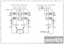
As you can see in the attached circuit diagram I used the capacitors across the LED’s. I remember your posts from some time ago about the positive results with these caps. And I think it’s a good idea to add these. I did no additional listening tests to verify this.
I have been looking at digital volume controls such as Maxim DS1669 and many others to control the current sources, but these devices have problems with currents up to 10mA. Perhaps I will jump on that later. For now the DACT is a simple (but expensive) solution.
1543:
I am very happy to hear that you have the same feeling about the sound of series/shunt LDR. Your description is exactly how I experience it. Try the CCS version. You will be amazed!
Badge:
Matching is quite simple. I ordered 10 pieces from Allied. Selected the 4 best of them for a future project and used the 4 next best for this project. You can add an optional potentiometer as shown across one of the LED’s to get them perfectly matched. I measured errors of less than 0.2 dB over the whole range. No conventional potentiometer (except stepped attenuators) can do that.
Attachments
Badge said:Peter, how closely do the components in you CCS need to be matched? I am referring to the series/shunt layout.
Badge, the matching of the LDR's (NSL-32SR2S) will be the same chore, regardless of what system is used to power the led section.
Cheers George
> LED’s. I remember your posts from some time ago about the positive results with these caps.
Maybe my understanding is incorrect, but the cap basically makes the voltage across the LEd constant and supplies any small current fluctuations required to achieve that, so doesn't it destroy the entire purpose of constant current drive at all (i.e. the LEDs are being supplied by the current source AND the caps) ?
> how closely do the components in you CCS need to be matched?
I think he was asking how well matched the TLV431s, BC550s, the 330Rs, the 120Rs and log pots, ..... had to be.
If that was the question, I think they need to be well matched.
But then that is easy enough in comparison to the LDRs.
Patrick
I buy my metal film resistors from Rapid online.
They are far better specified than the dale/vishay example and they are 20times cheaper.
If you want quality metal films then look to Holco for a similar price to the Allied retail. The Holco is even better specified than the Rapid. +-0.1% and 25ppm/C
They are far better specified than the dale/vishay example and they are 20times cheaper.
If you want quality metal films then look to Holco for a similar price to the Allied retail. The Holco is even better specified than the Rapid. +-0.1% and 25ppm/C
- Home
- Source & Line
- Analog Line Level
- Lightspeed Attenuator a new passive preamp