pietjers said:George:
No only small values with a total of about 1.5uF. The power amplifier is a hybrid design with bipolars in the output stage. It has a high input impedance of 470 kOhm.
Peter
Hi Peter,
can you share details of your hybrid amp?
I also have a hybrid made of a Aikido front end and a diamond buffer as output stage.
Cheers
Andrea
")
Sorry for being such a late-comer to this thread. This is a very nice attenuator concept.
I haven't read the entire thread, yet. (I hear your groans.) But I was skeptical about the claim of constant output impedance (post #4), since the output impedance is basically just the resistance across the shunt LDR, which must vary in order to sum with the series LDR's resistance, to try to get a constant input impedance.
I'm sure that that's probably been "asked and answered and beaten to death", already. But I did make a Spice model for the NSL-32SR2 optocoupler, and ran some LTspice simulations of the Lightspeed Attenuator circuit, plotting the LDR and input and output impedances, and the attenuation, etc.
With no source or load impedances connected, and the 100k pots (still using the original two-ganged-pots version) varying from one extreme to the other, for my model the input impedance starts at about 15k at full attenuation, then falls to about 10.7k, and then climbs back to about 14k at minimum attenuation. The output impedance changes from about 40 Ohms at full attenuation to about 14k Ohms at minimum attenuation.
If I connect 100k from an output to Gnd and 50 Ohms from the corresponding input to Gnd, then the input impedance starts at about 26k, rises to about 560k, and falls back to about 26k. The output impedance goes from about 38 Ohms (at max atten) to about 14k Ohms (at min atten).
I will provide a link to my 32SR2 Spice model, and my LTspice files for the attenuator, et al, shortly, so others can check to see if I have made any blunders. The model and circuit files should also be very helpful for anyone who wants to experiment with optocoupler attenuator circuits.
Note that my 32SR2 optocoupler spice model could be improved. I just enlarged and printed the response curve and hand-measured the datapoints. And I noticed that relatively small changes in the LDR response curve CAN make a noticeable difference in the attenuator circuit results. One other known problem with the optocoupler model is the LED model that is used in it. I just used one that was included with LTspice. But substituting other LED models does change the attenuator circuit results, somewhat. So a better LED model needs to be found. (I will also include my 32SR2_test circuit, which plots the response curve in the same format as it was given on the Silonex website.)
The section entitled "Defined Attenuation Law", at http://www1.silonex.com/audiohm/levelcontrol.html , looks interesting. They present a circuit that can be used to linearize the response of an LDR (the top section only, of the circuit shown). Unfortunately, it looks like they "left out" some components. It looks like C1 needs a resistor in parallel with it. And a resistor between the diode and the transistor's base seems helpful. And their resistor values need to be changed, if using the 32SR2 instead of the 32SR3. Also, note that the value of R6 was not specified. It probably helps to linearize the LDR's response. (Maybe an analog of the classic thermistor-linearization equation would work, to calculate the value of R6.)
I have just started on it, but have so far managed to cobble together a series-shunt optocoupler attenuator circuit that uses one similar linearization circuit for each channel's two optocouplers. Early results look promising. But I have nothing worth reporting, yet.
My LTspice simulation files for the NSL-32SR2 and the Lightspeed Attenuator MkII are downloadable by right-clicking on the following link and selecting "Save target As". Download size is about 6 kB.
http://www.fullnet.com/~tomg/OptoAtten.zip
The Lightspeed Attenuator MKII simulation circuit's file is named ATTENUATOR_test3.asc. A plot-settings file is included, so that, when run, it should automatically plot one channel's input impedance, the impedances of the two LDRs, and the ratio of the output level to the input level. It is currently set to sweep the pots over a 2-second period. Setting the period to 10 seconds gives a slightly-more-accurate set of plots.
The NSL-32SR2_PLOT.asc circuit will generate a plot of the LDR resistance versus the LED current, with a format similar to that of the plot produced by clicking of the "Figure 4" link, at http://www.silonex.com/audiohm/constants.html . The NSL-32SR2's model is an LTspice circuit, in a file named NSL-32SR2.asc. Its symbol is in file NSL-32SR2.asy. (Erratum: In the NSL-32SR2.asc file, the preceding link is given with the suffix "htm", instead of "html". The "htm" version will not work.)
Note that you would need the LTspice simulation software installed, to be able to use my simulation files. LTspice is available as a free download, from linear.com. Or, right-click on the following link and select "Save Target As", to download the executable Windows-version LTspice installation file directly:
http://ltspice.linear.com/software/swcadiii.exe
measured i/p & o/p impedances can be found here
http://www.diyaudio.com/forums/showthread.php?postid=1157216#post1157216
In this regard this LDR is not significantly different from any other pot.
mike
http://www.diyaudio.com/forums/showthread.php?postid=1157216#post1157216
In this regard this LDR is not significantly different from any other pot.
mike
Got my proto PCB and populated it this morning... One thing I overlooked was the LDR to GND connection. I used the PSU GND instead of the jack GND (really bad idea, horrible hum at low volumes). I think it's worth noting because it's a simple mistake to make when you have a laps in attention during PCB design. I'll pull the GND legs of the LDR tonight and wire them to the jack gnd to retest.
mikelm said:measured i/p & o/p impedances can be found here
http://www.diyaudio.com/forums/showthread.php?postid=1157216#post1157216
In this regard this LDR is not significantly different from any other pot.
mike
Hi mike,
It looks like they will vary, depending on the impedances of whatever is connected to the input and output. I was able to get widely-varying ranges of input impedance (measured from input to input's ground), by using different source and load impedances in my model.
-----
I also saw this, from georgehifi, in post #540:
"Mike the way to measure the output impedance is not how you have done, from output to ground with a DMM.
It is the total series resistance from the output (Lightspeed) to the source (CD) or (input Lightspeed) that is the output impedance of the Lightspeed."
If we agree with that definition of output impedance, then I guess it would correspond to the impedance of the series LDR that the input connects to, in parallel with: the source impedance in series with the paralleled shunt LDR and load impedance. For my 100k load and 50 Ohm source example, the "output impedance", when defined that way, goes from about 50 Ohms to about zero Ohms, as the attenuation goes from max to min, in my simulation model.
Greyskale said:Got my proto PCB and populated it this morning... One thing I overlooked was the LDR to GND connection. I used the PSU GND instead of the jack GND (really bad idea, horrible hum at low volumes). I think it's worth noting because it's a simple mistake to make when you have a laps in attention during PCB design. I'll pull the GND legs of the LDR tonight and wire them to the jack gnd to retest.
Yup. Ouch.
For anyone interested in simulating such effects, and for all those here who are interested in the effects of different types of power supplies, bypassing schemes, etc, it can be done by substituting an actual power supply circuit in place of the ideal 5V DC source I used, and then inserting wire and trace impedances into the model. You can then see the effects of sharing the wrong ground returns, etc. I have a convenient setup for doing that in LTspice, in some of the schematics at http://www.fullnet.com/~tomg/gooteesp.htm . You can just download a schematic file and then copy and paste the "star ground" section into your own simulation schematic. It makes it easy to implement the sharing and un-sharing of ground returns, etc, to experiment.
gootee said:If we agree with that definition of output impedance, then I guess it would correspond to the impedance of the series LDR that the input connects to, in parallel with: the source impedance in series with the paralleled shunt LDR and load impedance. For my 100k load and 50 Ohm source example, the "output impedance", when defined that way, goes from about 50 Ohms to about zero Ohms, as the attenuation goes from max to min, in my simulation model.
The LDR's do not go to zero in the same way that a pot does so we do not see the figures going to zero.
my figures are valid enough to see what is happening.
A high o/p impedance would have to be added to the "full volume" figures.
mike
gootee said:If I connect 100k from an output to Gnd and 50 Ohms from the corresponding input to Gnd, then the input impedance starts at about 26k, rises to about 560k, and falls back to about 26k. The output impedance goes from about 38 Ohms (at max atten) to about 14k Ohms (at min atten).
Gootee, hi welcome, I only had a chance to read to here but I think you need to do some re-measuring, the output that you have simulated (50ohms to ground) for the source is not represenitive of a source with 50ohm output impedance, the 50ohms is the series resistance from the source not what goes to ground, sorry back the the bench.
Cheers George
mikelm said:
The LDR's do not go to zero in the same way that a pot does so we do not see the figures going to zero.
my figures are valid enough to see what is happening.
A high o/p impedance would have to be added to the "full volume" figures.
mike
Hi mike,
I'm not trying to question your impedance figures. I'm mostly interested in questioning my modeling.
I am actually well-aware that the LDR resistance doesn't go quite to zero, having just transcribed the whole response-plot into a spice model, and having used another very-similar component in a non-audio commercial equipment design, in the past.
I guess maybe I should not have written "to about zero". But the impedance plot that I was discussing did go ALMOST to zero, in the simulation that I described (for which I have made the modeling tools public, here, by the way). It looks like my methodology was erroneous, for that particular impedance-plotting simulation (i.e. 50 Ohms from InR to gnd, to simulate source impedance, which was a stupid mistake). But everyone is free to try it for themselves, so they can help to correct the modeling and methodology. It should be helpful to everyone if we can get a model setup that more-or-less agrees with measurements.
Having just read georgehifi's post (the one after this one), it looks like I still didn't have the source impedance placed correctly. Trying it again, with 50 Ohms in _series_ with InR, and 100K from OutR to OutR_Gnd, and measuring impedance between OutR and InR, I'm seeing it change from near 15K to near zero, as the attenuation changes from the minimum output setting to the maximum output setting (almost exactly the same as the impedance across the shunt LDR paralleled with the 100K load, in this case).
georgehifi said:
Gootee, hi welcome, I only had a chance to read to here but I think you need to do some re-measuring, the output that you have simulated (50ohms to ground) for the source is not represenitive of a source with 50ohm output impedance, the 50ohms is the series resistance from the source not what goes to ground, sorry back the the bench.
Cheers George
Thanks George.
<grin> It was even worse than you thought! I re-created what I did, for the input impedance plot that went from something like 26k to 560k and back to 26k. It turns out that I had inadvertently placed the 50 Ohm resistor between the input and the _output_ (i.e. InR and OutR)!
With 50 Ohms in series with InR, and 100K from OutR to Gnd, maybe it's at least _somewhat_ more-reasonable looking: Input impedance (plotted by dividing voltage plot by current plot) goes from around 15K to about 10.4K (at 40% to 60% output level) and then back up to about 12.7k at the full-output setting. Since those figures are quite a bit lower than the ones mikelm gave in post # 535, I assume that my NSL-32SR2 spice model, or my circuit, needs to be tweaked. (I did notice that if I lower the power supply voltage from 5v to 3.3 volts, I get a roughly-similar input impedance level, with 50K, 31.5K, 32.5k.)
There's a pretty good chance that the LED model, inside my NSL-32SR2 model, needs to be changed. Based on a comment on the Silonex website, I think it should be a model for an Aluminum Gallium Arsenide (AlGaAs) type of LED. If anyone knows of a manufacturers' (or other) website that has a selection of AlGaAs LED models, please let me know. I'll also try to email Silonex, to see if they'll give me any hints.
Close to mine
gootee said:[
With 50 Ohms in series with InR, and 100K from OutR to Gnd, maybe it's at least _somewhat_ more-reasonable looking: Input impedance (plotted by dividing voltage plot by current plot) goes from around 15K to about 10.4K (at 40% to 60% output level) and then back up to about 12.7k at the full-output setting.
Tom,
These numbers are pretty close to what mine measure. The actual measured impedance is controlled by two factors:
1. The grade of the LDR. They have ones that have differing resistances at fixed currents. The higher grades measure higher impedances.
2. The measured value of the pots. I use pots to closely match up the impedances.
Using B or C grade LDR will give a lower measured impedance compared to E or F grade.
Using a 95k inplace of a 105K pot will also give a lower measured impedance.
Glad to see you take the time to model all this up. Build one up, you will like it.
Georgehifi has his commercial units where they measure around 7K average. I also got close to that value. So used dual 250K pots and paralleled the tracks. This way the impedance comes out around 10K.
George
Re: Close to mine
Panelhead said:gootee said:With 50 Ohms in series with InR, and 100K from OutR to Gnd, maybe it's at least _somewhat_ more-reasonable looking: Input impedance (plotted by dividing voltage plot by current plot) goes from around 15K to about 10.4K (at 40% to 60% output level) and then back up to about 12.7k at the full-output setting.
Tom,
These numbers are pretty close to what mine measure. The actual measured impedance is controlled by two factors:
1. The grade of the LDR. They have ones that have differing resistances at fixed currents. The higher grades measure higher impedances.
2. The measured value of the pots. I use pots to closely match up the impedances.
Using B or C grade LDR will give a lower measured impedance compared to E or F grade.
Using a 95k inplace of a 105K pot will also give a lower measured impedance.
Glad to see you take the time to model all this up. Build one up, you will like it.
Georgehifi has his commercial units where they measure around 7K average. I also got close to that value. So used dual 250K pots and paralleled the tracks. This way the impedance comes out around 10K.
George
Hi George (Panelhead),
Thanks for the great reply. Your impedance numbers, and your explanation of the impedance-variance factors, make me feel a little more comfortable with the simulation model.
Now I'm wondering what the "ideal" impedances would be.
But if you just wanted them all as low as possible, it seems like you could just boost the power supply voltage.
(Not that that's necessarily the case, but...) Having a ready simulation model is extremely handy, for looking at things like that. It took me literally just a few seconds to change the supply from 5v to 6v and re-run the plots. Still using 50 Ohms source impedance and 100k Ohms load, the input impedance now varies from about 10.1k to 6.8k to 8.9k, while the output impedance varies from about 10.1k to about 82 Ohms. And the output/input ratio still goes all the way from 0.003 to 0.991.
I tried a 7v supply, just for fun, and got input R varying from 7.1k to 5k to 6.5k, and output impedance going from 7.1k to 85 Ohms, while output/input ratio went from 0.0045 to 0.988. For 8v, input R goes from 5.5k to 3.8k to 5k, and output R goes from 5.4k to 84.6 Ohms, while output/input ratio varies from 0.0058 to 0.984.
If you look at my attenuator simulation schematic, you'll see a line that has ".param vsupply=5", on which you can right-click, to edit the supply voltage.
But it gets way better: I accidentally left in another line, below that, that has ";.step param vsupply 5 4 0.5". The leading semicolon means that that line is "commented out", and does nothing. BUT, if you un-comment it (and comment-out the other vsupply line), then you can click the "Run" button, just once, to make the simulator _automatically_ step through a whole range of values, and show _multiple_ curves, for each plot!
For example, to try supply voltages from 5 volts to 8 volts, in 0.5-volt increments, you could use:
.step param vsupply 5 8 0.5
That's just an example. I don't even really know if it makes sense to vary the supply voltage, in this case. But the _concept_ can be applied to almost anything on any schematic.
-----
Well, I probably WILL build one. But first I think I'll see if I can get the linearization scheme working, which might make it possible to have the input impedance be much more constant. In one of my first few attempts, so far, I got one where the input impedance only varied by a couple hundred Ohms from 9k, over the whole range of pot settings. How desirable IS it, to have a constant input impedance, anyway?
I was able to correct the error on my PCB tonight and test out the lightspeed (only briefly though). What a difference! silent, NO coloration and to be honest, it sounds like I'm getting better separation now... deeper perhaps. I will give it a good listen tomorrow and post again, but as it stands, I'm ecstatic about this design!
Oh, and with George's permission, I will correct the errors on the layout and share it here.
Oh, and with George's permission, I will correct the errors on the layout and share it here.
Greyskale said:I was able to correct the error on my PCB tonight and test out the lightspeed (only briefly though). What a difference! silent, NO coloration and to be honest, it sounds like I'm getting better separation now... deeper perhaps. I will give it a good listen tomorrow and post again, but as it stands, I'm ecstatic about this design!
Oh, and with George's permission, I will correct the errors on the layout and share it here.
Ye have been converted, you have my blessings my son, go forth and fornicate till your hand falls off, or blindness sets in, so long as you don't try to make a buck out of it.
Cheers George
Patrick, Mike, Panelhead,
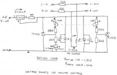
Two days ago I promised to share a drawing of a real voltage source version of the Lightspeed volume control. This is a design idea that I never built because I am afraid that the temperature dependency of the LED’s could be an issue. But perhaps it is not a problem at all, who knows? See the attached file for details.
It’s shunt regulator fed by a constant current source. The resistance values are calculated to be able to use a 100k potentiometer because that is what almost everyone is using now. But it’s perhaps better to divide all resistor and potentiometer values by 10, so the circuit would be less highohmic. A trim potentiometer is added to be able to match the optocouplers. I think that there is no need for heavily selected optpcouples to get everything perfectly matched. Likely it can be powered from a 5V source but that will be on the tight side because of an almost 3V voltage dropout of the current source.
When someone is going to try it, please check the output for stability. TLV431’s can oscillate under certain circumstances (but are usually dead quit).
Peter
Attachments
I've made all the necessary changes to the layout last night and will post it here later today. It's George's design with added 100uf caps in parallel with the LED/LDRs. It does include the 5v regulator and PSU caps on board as well and is designed in such a way to allow the user to build it with the series resistor shunt LDR if wanted (though I've not tested this and am beyond happy with my lightspeed as it is).
Listening impressions: I have been able to set aside a few hours to really listen to the lightspeed. So what do I hear? NOTHING! No change to the sound when the source is connected directly to the amp, or through the lightspeed (which is what I wanted) The sound is unchanged with one exception. I swear I'm getting better channel separation/wider sound stage!
Thanks George, for all your assistance!
- Home
- Source & Line
- Analog Line Level
- Lightspeed Attenuator a new passive preamp