excetara2, if your going to run a separate dac then chances are the output impedence will be fine on the dac.
The input impedence of the poweramp can be measured with a multimeter at the rca input (poweramp off), if the input is capacitor coupled then it has to be measured inside the amp after the cap. Tell us what power amp you have, I'm sure one of us will know the input impedence, that will save you measuring it.
Cheers George
Banned
Joined 2002
excetara2 said:Shouldn't be hard to measure it, but if you got it I have a Odyssey Stratos amplifier.
http://72.14.203.104/search?q=cache...yssey-Stratos+review&hl=en&gl=au&ct=clnk&cd=3[/url]
Your Stratos seams to be a standard 47k input impedence, should be no problem for a diy Lightspeed passive pre, just keep interconects below say one and a halve meters and try to use ones that are of low capacitance < 100pf per foot and all should sound great with your dac driving it all.
Cheers George
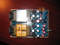
For those of you who emailed for a look of the internals, here it is, the potted off white block in the centre of the main board houses the 4 x led/ldr packages, the other board is the second regulation 5vdc board, and not in the pic is a regulated 12vdc plug pack.
Cheers George
Cheers George
Attachments
Badge, if you have followed the Lightspeed Attenuator circuit as I,ve posted, with a 5+VDC with the NSL-32SR2S and 100ohm resistors and 1k multiturn calibration pot all will work as stated.
Be carefull that the led side of the NSL-32SR2S is around the right way, the white dot is the negative of the Led and should go to ground, the other leg is naturally positive and goes to the 100k pot via the 100ohm resistors and the calibration pots.
If the NSL-32SR2S are a perfect match, you will not need the 1k calibration pot.
The led takes no punishment at all in these NSL-32SR2S and will blow if wired the wrong way around.
Hope all works out for you, keep me posted.
Cheers George
Look at the pots
The way that George wired these up is tricky. There is no ground going to the pot. I suspect this is why you are not seeing any voltage drop with pot rotation. Check the resistance as the pot is opened. It should increase. The 5 volts goes to opposides of the stereo pot so that one side decreases when the other "channel" increases.
The pot needs to be measured to make sure when closed, say 7 o'clock the series LDR is seeing a high resistance and the shunt is seeing no resistance.
George wires his is to connect the wiper to the other end. This way if the wiper goes open, the LDR will see maximum attenuation.
I have built mine, got it properly checked up. Now it needs connecting in circuit. It is a Lightspeed clone. Orginally was going to be just an attenuator. But thought what the heck, if people love it as a passive unit, I should at least listen to it as designed by George. Might change my opinion of passive preamps.
George (low fi)
Badge said:I am testing my circuit. I assumed the 100K pots would control the voltage? I am only seeing a very small drop in voltage at full attenuation. In fact, the voltage changes very little through out it's travel.
The way that George wired these up is tricky. There is no ground going to the pot. I suspect this is why you are not seeing any voltage drop with pot rotation. Check the resistance as the pot is opened. It should increase. The 5 volts goes to opposides of the stereo pot so that one side decreases when the other "channel" increases.
The pot needs to be measured to make sure when closed, say 7 o'clock the series LDR is seeing a high resistance and the shunt is seeing no resistance.
George wires his is to connect the wiper to the other end. This way if the wiper goes open, the LDR will see maximum attenuation.
I have built mine, got it properly checked up. Now it needs connecting in circuit. It is a Lightspeed clone. Orginally was going to be just an attenuator. But thought what the heck, if people love it as a passive unit, I should at least listen to it as designed by George. Might change my opinion of passive preamps.
George (low fi)
Spoke too soon
Once in chassis, I had similar problems. Mine has two stereo controls to give mono operation and allow channel balancing this way.
To get mine to operate as designed it required wiring the series element as normal, and then connected to the wiper and other end on the back section. No other connection allowed the series and shunt voltage to operate properly.
With 50K linear controls it measures 10K with pot in line and 70 ohms with just thw 121 ohm resistors. This should attenuate fine.
Got operating perfectly, midrange is about 4K series and 4K shunt. All my sources should handle 8K.
But assembling box, must have either lost a connection or shorted something. Even with a 10K series resistance and 70 ohms to ground it is LOUD. And opening the pot makes it even louder. Suspect the shunt diode supply is opened up. The bass is okay, and if the series was shorted it would not get louder as pot is opened.
Tomorrow is another day.
George
Badge said:George, I am having trouble following your dual attenuator description. Can you post a layout or send me a drawing? Thanks.
I'll draw up a better diagram today and have it posted by this evening.
Cheers George
Pots are maybe my problem.
Mine ate me up. I measured the pots and checked resistances so that I knew what was going on. Wired it up and the shunt and series impedances tracked together.
Must have tried six combinations to get it right. What is strange is that the series pot is connected with 5 volts on left pin, output on wiper. The shunt is on the rear section, with the 5 volt on wiper and the output on the right connector. Flipping the 5 volt to the right rear connector and taking output off the wiper works backwards. I cannot understand why this is directional. Seems that the resistance inbetween is the same either way.
You might try this on your pot also. It only took me an hour or so of scratching my head to get it working properly. I just thought I understood pots.
George
Ok here it is again, still not great but I'm no good with drawing, but everything is there and if built as per the drawing it will work perfectly, if not i suggest to give it up and buy one from me, at least I'll make a couple of bucks.
Remember if your NSL-32SR2S are a good match you will not need the 1k trimpots, if not you will only need the 1k trimpot on the channel that has the most gain to bring it into a match with the weaker channel, I only put trimpots on both channels in the drawing as a guide.
Cheers George
Remember if your NSL-32SR2S are a good match you will not need the 1k trimpots, if not you will only need the 1k trimpot on the channel that has the most gain to bring it into a match with the weaker channel, I only put trimpots on both channels in the drawing as a guide.
Cheers George
Attachments
Banned
Joined 2002
georgehifi said:Ok here it is again, still not great but I'm no good with drawing, but everything is there and if built as per the drawing it will work perfectly, if not i suggest to give it up and buy one from me, at least I'll make a couple of bucks.
Remember if your NSL-32SR2S are a good match you will not need the 1k trimpots, if not you will only need the 1k trimpot on the channel that has the most gain to bring it into a match with the weaker channel, I only put trimpots on both channels in the drawing as a guide.
Cheers George
What does the 5V's Do ?
jleaman said:
What does the 5V's Do ?
The 5vdc is controled by the 100k dual pot, that gives varible (give and take) voltage to the leds, which in turn varies the resistance of the LDR's.
Cheers George
Lightspeed Clone Playing this morning!
My cover fits tight over the pots and in installling it pushed two wires together. Fixed this morning, getting up at 4 am has its benefits.
It is now playing perfectly. With the volume all the way down there is a very low volume coming through, this is a 9K series and 80 ohms to ground voltage divider.
Sounded a little rough the first few minutes, now it is smoothed out fine. Good frequency balance. Decent slam.
Amp used right now is a loaner. It has 44k imput. My normal amp is 100K so it may improve when driving a higher impedance load.
Attachments
![dsc01655[1].jpg](/community/data/attachments/66/66313-371824a5f55d084a71dcc325b8d4f338.jpg)
All connected
This chassis has driveshafts to shorted the signal path. Since this is now a voltage controller it is not important. Does not hurt.
If pics are not clear enough the 5 volt goes in left side of front pot and out on wiper. Then in on wiper and out right side on the rear, shunt diode side. Must be my pots, but the polarity of these connections was important in my set up with linear pots.
The power supply is a 12v wallwart battery charger. The 17 volts feeds the first adjustable reg. This 10.5 volts feeds the second fixed reg. Used all parts laying around. Output is a very clean 5.06 volts.
Thanks George!!!
George
Attachments
![dsc01659[1].jpg](/community/data/attachments/66/66319-84f1f3c3dba93d6242f50ba8ee3ec862.jpg)
- Home
- Source & Line
- Analog Line Level
- Lightspeed Attenuator a new passive preamp