http://www.fortunecity.com/rivendell/xentar/1179/projects/aaphono/aaphono.html
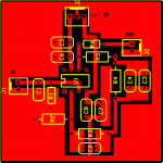
This is my first attempt at designing a PCB so go easy ok Its the Analog Addicts preamp without the coupling caps on the output. The resistors in the feedback loop are physically larger because the schematic calls for .1% tolerance. The .0047uf and .001uf caps are Wima MKP2 while the 47pf and 330pf are ceramic. Although maybe switching to silver mica could improve things.
This layout was done with ExpressPCB although I am trying to learn Protel. The learning curve is a bit steep. Any comments or criticisms are welcome.
This is my first attempt at designing a PCB so go easy ok
This layout was done with ExpressPCB although I am trying to learn Protel. The learning curve is a bit steep. Any comments or criticisms are welcome.
Attachments
hjelm said:c8 and c7 seem to be shorted? It seems that half the supply is shorted to ground at c7 and c6. I can find a path from the right side of the J1 to the middle pin of J1.
/regards
Indeed. A suggestion: move R3, C2 to the left of C7, C8. Then run the trace from R4 etc to R3 etc under C7, C8. Then you can vreate a good ground plane for the supply decoupling caps with short tracks.
Of course, a dual layer would make it even easier.
Jan Didden
- Status
- This old topic is closed. If you want to reopen this topic, contact a moderator using the "Report Post" button.
