jackinnj said:
The one difference which a transformer can make (particularly for a phono-preamp) is the energy it radiates itself -- EI cores and torroids have different patterns.
The other difference is that attibutable to from the tank circuit formed by the secondary inductance, the diode's capacitance AND the capacitance between primary and secondary windings. The ringing can be dealt with by placing a RC across each diode, or across the diode bridge. If you don't have the equipment to measure the transformer inductance, try using 10nF and 220R in series.
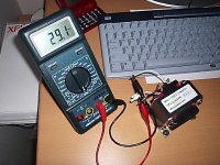
I am not sure how to measure this inductance and what all this really mean. I measure the secondary between V and center tap and it display 29.1mH when the multimeter set to measure L. See pic...The primary measured 1.22H if this mean anything?
Attachments
chris ma said:
I am not sure how to measure this inductance and what all this really mean. I measure the secondary between V and center tap and it display 29.1mH when the multimeter set to measure L. See pic...The primary measured 1.22H if this mean anything?
Short the two primary leads together, then measure the secondary inductance. Then measure the capacitance between the primary and secondary windings.
The manufacturer's datasheet for the diodes will specify a capacity at a specific voltage. for the MUR860 it should be 100pF at 30V.
the ringing frequency can be found from this formula:
F = 1/ [2* pi * sqrt (LC)]
where C is the sum of the diode capacitance and the interwinding capacitance.
the snubber resistor is then:
Rs = sqrt (L/C)
the snubber capacitor is then:
Cs = [2*pi*sqrt(LC)] /Rs
all of the above is clearly discussed on Jim Hagerman's paper "Calculating Optimum Snubbers". http://www.hagtech.com/pdf/snubber.pdf
This in turn is based upon a white paper which Cornell Dubilier put out.
don't forget that the units of millihenries are 10^-3, and picofarads are 10^-12.
(I am guessing you are using +/- 15 V rails, the diode capacitance is around 180pF at this voltage (capacitance varies inversely with voltage).
Rs = 3.3K
Cs = 2.2 nF
you can try a "before and after" to see if it makes a listenable difference.
(I am guessing you are using +/- 15 V rails, the diode capacitance is around 180pF at this voltage (capacitance varies inversely with voltage).
Rs = 3.3K
Cs = 2.2 nF
you can try a "before and after" to see if it makes a listenable difference.
Onvinyl said:chris ma,
if you encounter problems how to stuff the regulator boards i could help you out with the circuit for that specific boards.
and the AD825: is there any dip8 replacement that provides similar performance?
Rüdiger
Do you mind sharing how do you connect to the regulators. I am yet to make those two jumper wires that I can see from picture on the AOS site. These jumper wires are not mentioned in the schematic. Is the +ve load means the output +ve to the phono stage?
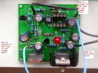
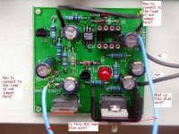
Please post a picture of a positive board that you have. Post both sides so I can follow the traces.
BTW, have you read the description of the original article from AudioXpress/Audio Amateur as yet? It will provide much insight to what is going on.
Also see this
http://home.comcast.net/~walt-jung/wsb/PDFs/Improved_PN_Regs.pdf
I'm busy this week, otherwise I could always head out your direction one evening next week and get it started.
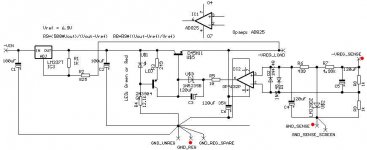
OK, it is confusing to someone who has not really understood what the heck the super reg is trying to do as yet since this regulator is unlike others you might have done before.
http://www.alw.audio.dsl.pipex.com/Manuals/ALWSR_rev2.9_Iss005s.pdf
Take some time tonite and read the assembly manual on connections.
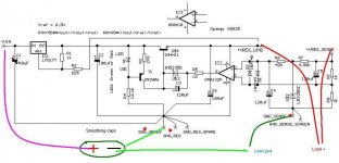
When you connect everything up in a "local" sense fashion, you are turning the super reg configuration into a more conventional power regulator. The voltage is maintained and regulated UP TO the output of the board itself.
When you connect everything up in the REMOTE sense configuration, you are regulating UP TO WHERE the remote sense is connected. This way, any impedances along the connections to the powered circuit is compensated for by the feedback. In essence you are EXTENDING the actual regulator power circuit RIGHT UP TO WHERE the IC actually is.
Since you are going dual mono P2P on the phono, this will likely be right up to the IC power connection. (Don't forget decoupling caps for the IC)
If you read the link supplied you'll get a better understanding of this down around page 24 or so. Due to the high bandwidth, the remote sense is best done using shielded wire.
I can't be specific on the tracking connection since I don't know exactly how AOS has done this on the board. In other words I don't know if the tracking feedback is connected remotely of from the return on the regulator itself.
Figure 4 should shed some light
http://www.alw.audio.dsl.pipex.com/Manuals/ALWSR_rev2.9_Iss005s.pdf
Take some time tonite and read the assembly manual on connections.
When you connect everything up in a "local" sense fashion, you are turning the super reg configuration into a more conventional power regulator. The voltage is maintained and regulated UP TO the output of the board itself.
When you connect everything up in the REMOTE sense configuration, you are regulating UP TO WHERE the remote sense is connected. This way, any impedances along the connections to the powered circuit is compensated for by the feedback. In essence you are EXTENDING the actual regulator power circuit RIGHT UP TO WHERE the IC actually is.
Since you are going dual mono P2P on the phono, this will likely be right up to the IC power connection. (Don't forget decoupling caps for the IC)
If you read the link supplied you'll get a better understanding of this down around page 24 or so. Due to the high bandwidth, the remote sense is best done using shielded wire.
I can't be specific on the tracking connection since I don't know exactly how AOS has done this on the board. In other words I don't know if the tracking feedback is connected remotely of from the return on the regulator itself.
Figure 4 should shed some light
jackinnj said:don't forget that the units of millihenries are 10^-3, and picofarads are 10^-12.
(I am guessing you are using +/- 15 V rails, the diode capacitance is around 180pF at this voltage (capacitance varies inversely with voltage).
Rs = 3.3K
Cs = 2.2 nF
you can try a "before and after" to see if it makes a listenable difference.
Hi,
Do you mind show me how you get the Rs=3.3k with the formula from the optimum snubber pdf ? I am still confused with the number of Zeros

Help with maths
Please see if I have any mistake here? I am not trying to prove you wrong I just want to make sure I understand how to use the formulas so that when I use a different transformer I can calculate new parts. That's why I am not sure how Carlos can recommend all those snubber values without knowing all different transformers that people are using in the chip amps.
See my calculation here:
L=2.91mH
C=68.2pF + 180pF=248.2pF
L=2.91mH=0.0291H
C=248.2pF=0.0000000002482F
Rs=sqrt(L/C)
Rs=sqrt(0.0291/0.0000000002482)
Rs=sqrt(117244157.937147461)
Rs=10827.9341
Cs=[2*pi*sqrt(LC)]/Rs
Cs=[2*(22/7)*sqrt(0.0291*0.0000000002482)]/10827.9341
Cs=0.000000000156010404798
If 10^-9 = n
Then Cs=1.56nF
So I get
Rs=10k8
Cs=1.56nF
Sorry that I have only O level maths and that was grade B I got many many many years ago!!
Hi Chris,
almost there, only lost one decimal place.
3k42 & 1n56F therefore use 3k3 & 1n5F.
Try using a calculator with Exp function then it's much easier.
e.g. 2.91mH enter 2.91 Exp 3 +- => .00291H
The exp multiplies 2.91 by 10^3 (or 1000) +- changes the sign from + to - which gives 2.91 * 10^-3
and 68.2pF is 68.2 Exp 12+- => 68.2 *10^-12
This way you don't have to keep count of all the zeros
I used the formulae from your last post, check them again to be sure. I am very surprised that the resistor is so large but maybe this is due to the smallness of the transformer.
Congratulations on taking on board such a complex piece of research with limited maths abilities. As a result of you sharing your work I have learned something new as well.
AndrewT said:Hi Chris,
snip.... I am very surprised that the resistor is so large but maybe this is due to the smallness of the transformer.
snip..l.
Can I assume that the bigger the transformer gets the value of the resistor would tend to be smaller?
- Status
- This old topic is closed. If you want to reopen this topic, contact a moderator using the "Report Post" button.
- Home
- Source & Line
- Analog Line Level
- Is regulated PSU for phono preamp a MUST?