The OP and at least one participant of this cool thread asked for details on some of my discrete op-amp designs.
That thread is here: Purple Gain:a discrete opamp
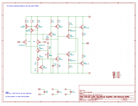
So a little context, these were designed for my tape amplifier project. There are 4 variants; one is yet untested, and I will share the one I am currently using in the front end in this post.
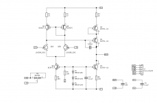
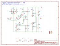
They have LSK389 dual jfets in the front end, but are otherwise pretty traditional.
The version I have shared is the high gain iteration that is used in the first stage of the tape amplifier which needs a lot of gain at low frequencies.
I've attached the .asc file.
That thread is here: Purple Gain:a discrete opamp
So a little context, these were designed for my tape amplifier project. There are 4 variants; one is yet untested, and I will share the one I am currently using in the front end in this post.
They have LSK389 dual jfets in the front end, but are otherwise pretty traditional.
The version I have shared is the high gain iteration that is used in the first stage of the tape amplifier which needs a lot of gain at low frequencies.
I've attached the .asc file.
Attachments
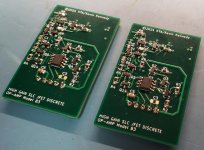
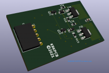
Here is the original which has a transconductance amplifier output and is very simple.
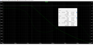
OLG is >75dB and -3dB open loop is a bit above 3kHz.
I changed gender of the connector after I built the first pair - these are in use in a buffer I use to bring up the output level of my Sony KA-7 ES cassette deck to levels compatible with the rest of my system.
OLG is >75dB and -3dB open loop is a bit above 3kHz.
I changed gender of the connector after I built the first pair - these are in use in a buffer I use to bring up the output level of my Sony KA-7 ES cassette deck to levels compatible with the rest of my system.
Attachments
They're quite good - I use a few of the transconductance output version as buffers for various cassette decks (Sony KA-7ES and KA3-ES) that have output levels too low to play well with my system which is designed for reference level of +6dBv.
Use a pair in a pre-amplifier in the home office which works well.
There are 3 variations in use in my tape pre-amplifier.
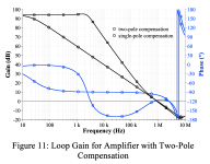
Interestingly there is a 4th, designed about 6 months ago which has amongst other things two pole compensation. I have a bunch of PCB for it and have not built any to date. I don't think I have my head fully wrapped around the two pole compensation which also incorporated some other things including a change to lower the Q in the transition region where it starts to roll off. The phase flip where the compensation starts the open loop roll off makes me uncomfortable and I am going to study this and the values I originally selected. Doug Self's explanations of two pole compensation are not quite enough for me to intuitively understand how to apply it. I am still more comfortable with the simpler and reasonably intuitive miller compensation.
I have a tendency to overcompensate them, but in practice they achieve about 30V/us slew rates, and unity gain bandwidths of 8 - 10MHz. Distortion is lower than the limits of my Amber 3501A but I have not fired up the RTX to do more comprehensive measurements as I am usually in a rush and the software interface is work to master and need to work on that.
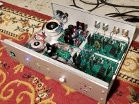
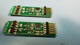
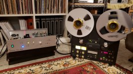
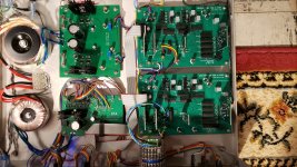
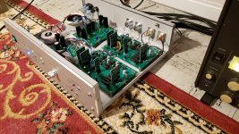
I've attached a few pictures of the end application. The voltage regulators are also discrete op-amp but all BJT, no fets. I am very happy with the performance of the tape amplifier, but there will be no more - insufficient (outside) interest to justify continuing to develop it.
Use a pair in a pre-amplifier in the home office which works well.
There are 3 variations in use in my tape pre-amplifier.
Interestingly there is a 4th, designed about 6 months ago which has amongst other things two pole compensation. I have a bunch of PCB for it and have not built any to date. I don't think I have my head fully wrapped around the two pole compensation which also incorporated some other things including a change to lower the Q in the transition region where it starts to roll off. The phase flip where the compensation starts the open loop roll off makes me uncomfortable and I am going to study this and the values I originally selected. Doug Self's explanations of two pole compensation are not quite enough for me to intuitively understand how to apply it. I am still more comfortable with the simpler and reasonably intuitive miller compensation.
I have a tendency to overcompensate them, but in practice they achieve about 30V/us slew rates, and unity gain bandwidths of 8 - 10MHz. Distortion is lower than the limits of my Amber 3501A but I have not fired up the RTX to do more comprehensive measurements as I am usually in a rush and the software interface is work to master and need to work on that.
I've attached a few pictures of the end application. The voltage regulators are also discrete op-amp but all BJT, no fets. I am very happy with the performance of the tape amplifier, but there will be no more - insufficient (outside) interest to justify continuing to develop it.
Attachments
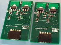
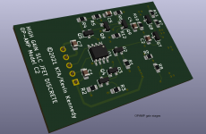
So here is the two pole compensated version. Based on a quick read through the AES paper I made some minor improvements to the compensation. (Rayma - thank you, it helped quite a bit.)
This is intended primarily for the front end tape amp, where the additional OLG will improve the accuracy of the LF EQ where quite a lot of gain is required (around 70dB 50Hz for NAB, and almost 80dB for IEC at 20Hz)
Off the top of my head I do not remember where the others roll off but it is certainly below 20Hz.
The extra gain margin would of course improve distortion performance significantly across the full frequency response range of the pre-amp.
As I have remarked I have the boards on hand and should have most of the parts required. Possibly I will build some this winter.
Attachments
I suspect the only thing I'm going to hear is an improvement in LF EQ accuracy in the tape amplifier.
I'm not really good at subjective description of my designs, and always what I hear is subject to my less than entirely unbiased/reliable opinion, not to mention antique hearing. I'll do my best to describe (as my subjective listening based opinion) as well as provide some measurements. I am a bit of a fence straddler believing in the merit of measurements, but not ignoring my subjective impressions either.
The current ones are quite transparent, the major differences are really just in OLG and output current capability.
This one has sufficient phase margin to use safely in unity gain applications, some of the earlier designs are really intended for applications with at least 6dB of noise gain. (Unity gain inverting, and +6dB non-inverting) I have used them all in circuits with as little as 10dB of noise gain without any issues.
I've attached a few pictures of the end application. The voltage regulators are also discrete op-amp but all BJT, no fets. I am very happy with the performance of the tape amplifier, but there will be no more - insufficient (outside) interest to justify continuing to develop it.
Kevin, what connector type do you use for those plug-in boards? I've been looking for some but the ones I found were not very stable, mechanically.
Jan
Post how they sound when you compare them with the others.
Interesting design.
I would be more interested in the hard facts, like distortion and noise.
")
I'm going to take a look at the paper, thank you for sharing it.
Please, let me put my 50 cents in the moneybox.
Attached.
So here is the two pole compensated version.
Let's be fair, first or second order compensation around main gain stage (VAS) is a slow strangulation. Yes, second order keeps much more feedback depth at higher audio band part, but why do really we use it?
The main issue is to dropdown gain for having safe phase margin at some frequency, which is safely passes output stage. So really we do move unity gain frequency as down as possible for having uncinditionally stable amp.
But why namely around VAS?
It's simplest way to provide stability.
Just put 100 pF around VAS stage and you're in.
Are there a more sophisticated way?
Of course.
First of we need to understand VAS-OPS interaction.
Follower-style OPS have some input capacitance (usually low, 10-30 pF in case of EF-triple) and very high input impedance.
So VAS output impedance (a resistor from VAS output to ground) usually in range of dozens of kOhms or one MOhm. It sets gain of VAS. What capacitance we really needs at this point? Easy. Such a capacitance must stabilize VAS-OPS interaction pole. I.e. it must be 3x to 5x times as ((OPS input capacitance) + (VAS output capacitance)). Really, that's more than enough.
Setting this capacitance to ground instead of VAS input removes VAS gain multiplication and hugely improves HF gain.
But now our amp itself becomes decompensated and needs a different external compensation than usual unconditionally stable amp.
Let me show what we can do by attaching perfect Jim Karki's article.
Using such an approach we can remove some asphixation from the amp's VAS stage (providing a way less compensation nominals) and add some external poles/zeros to conditionally stabilize the whole stage.
Doing this easily allows us to pick at least 20-30 dB of feedback depth and accordingly decrease THD. View attachment slyt174_Jim Karki, Using decompensated opamp.pdf
LSK389, is that the dual 170? If so I've used them a couple of times before. Once even as a diamond buffer IIRC. Nice to work with, doesn't add anything.
Yup that's the one. Matching could be a bit better, but is adequate for the application.
Kevin, what connector type do you use for those plug-in boards? I've been looking for some but the ones I found were not very stable, mechanically.
Jan
Hi Jan,
These seem reliable from a contact standpoint, but unless they are fully seated on the mating pins they are not that stable - may not be a big improvement over what you are using. When I am sure all is well I usually secure with a dab of hot melt glue.
www.digikey.com/en/products/detail/sullins-connector-solutions/PPPC051LGBN-RC/775938
This is the current version of the connector I have been using.
Let's be fair, first or second order compensation around main gain stage (VAS) is a slow strangulation. Yes, second order keeps much more feedback depth at higher audio band part, but why do really we use it?
The main issue is to dropdown gain for having safe phase margin at some frequency, which is safely passes output stage. So really we do move unity gain frequency as down as possible for having uncinditionally stable amp.
But why namely around VAS?
It's simplest way to provide stability.
Just put 100 pF around VAS stage and you're in.
Are there a more sophisticated way?
Of course.
First of we need to understand VAS-OPS interaction.
Follower-style OPS have some input capacitance (usually low, 10-30 pF in case of EF-triple) and very high input impedance.
So VAS output impedance (a resistor from VAS output to ground) usually in range of dozens of kOhms or one MOhm. It sets gain of VAS. What capacitance we really needs at this point? Easy. Such a capacitance must stabilize VAS-OPS interaction pole. I.e. it must be 3x to 5x times as ((OPS input capacitance) + (VAS output capacitance)). Really, that's more than enough.
Setting this capacitance to ground instead of VAS input removes VAS gain multiplication and hugely improves HF gain.
But now our amp itself becomes decompensated and needs a different external compensation than usual unconditionally stable amp.
Let me show what we can do by attaching perfect Jim Karki's article.
Using such an approach we can remove some asphixation from the amp's VAS stage (providing a way less compensation nominals) and add some external poles/zeros to conditionally stabilize the whole stage.
Doing this easily allows us to pick at least 20-30 dB of feedback depth and accordingly decrease THD.
There's a LOT of subtlety to what you propose here. It's another form of two-pole compensation. You've got one pole in your lag compensation network on the output of the VAS, and a pole and a zero in your external network between the two input terminals. I don't see the advantage over traditional TPC around the VAS. You end up with less DC open-loop gain because of the additional load on the VAS.
A possible benefit, which I think you allude to, is that you make the loading on the VAS more consistent since you swamp the OPS input impedance with an explicit RC network. I'm not sure how this plays out as a subjective improvement in practice.
As I said in that other thread, I'm not trying to get into a chest-thumping debate. People are (rightfully) proud of all the work they did learning their EE theory and sometimes these discussions turn into ego-fests. Not my intent.
It would be cool if you could generate some schematics and Bode plots. It would make things clearer.
There's something I really wonder about and haven't figured out yet. That's the effect of compensation on the input and output impedance of the VAS. Shunt feedback around the VAS lowers its input impedance. The derivation for TPC describes the input as a virtual ground. This is true at higher frequencies, where there's lots of feedback, and all or most of the IPS output current flows into the compensation network. But, evidently, with TPC, or lag compensation on the output, you have much less current flowing into the base of the VAS transistor as midband. I would think the stage then operates much more like a voltage amplifier and not a transimpedance amplifier. The papers I've read sometimes touch lightly on this (i.e., mentioning that TPC loads the IPS a lot less), but don't really dig into it in detail. The other thing, I believe, is that TPC puts a higher load on the VAS output, though this can be mitigated by having a 10:1 ratio of compensation capacitors, with the smaller one on the output side. Again, I haven't seen a good analysis of this. Most of the papers just focus on the increase in available global feedback, but don't talk about the fact that you are necessarily reducing the amount of linearization due to feedback around the VAS.
I dunno, man. This is a very esoteric subject. I almost feel like an idiot talking about it.
I don't think I have my head fully wrapped around the two pole compensation which also incorporated some other things including a change to lower the Q in the transition region where it starts to roll off. The phase flip where the compensation starts the open loop roll off makes me uncomfortable and I am going to study this and the values I originally selected. Doug Self's explanations of two pole compensation are not quite enough for me to intuitively understand how to apply it. I am still more comfortable with the simpler and reasonably intuitive miller compensation.
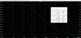
Kevin, you're talking about the saddle-backed shape to the phase curve with TPC (below). Conventional wisdom says we want the loop phase margin to be greater than 45-60 degrees anywhere the loop gain is greater than unity. TPC makes us nervous because the phase dips close to -180 degrees when the amp still has loads of gain. We think, "If the loop phase hits -180 degrees and we have greater than unity gain, the amplifier will oscillate." Turns out this isn't true. As long as the phase comes back up again, and there is sufficient phase margin at the unity-gain crossover frequency, the amplifier will be stable. That's true even if the phase shift exceeds -180 degrees at midband.
There are some potential negative consequences to this, and Miller will always be safer if you can live with its own tradeoffs.
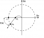
The Bode plot is a simplified view of the loop transfer function, insofar is it only shows the gain and phase response to pure sine wave signals. The Nyquist stability criterion takes into account the closed-loop response to signals on the complex frequency plane. (Complex frequencies have both sinusoidal and exponential characteristics, in essence).
We really want a Nyquist plot of the loop transfer function. The phase margin is as shown, and the gain margin is the distance along the real axis between the points labeled "-1" and "wc." Unfortunately, the explanation of all this, I think, is beyond the scope of this discussion, and pushes the limits of my own math background.
Attachments
See post #9 of Opamp with open loop gain of 1,000,000,000,000,000. for a simple conditional stability demonstrator circuit.
for a simple conditional stability demonstrator circuit.Yes. The irony is, we usually think that reducing loop gain increases stability. But in the case of your demonstration, reducing loop gain can actually induce oscillation. I believe this explains why I have problems with instability on clipping in my TPC headphone amplifier.
- Home
- Source & Line
- Analog Line Level
- Playing at Discrete Op-Amp Design