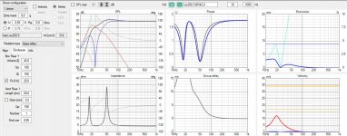
Hi, I am simulating a vented cab in Vituix Cad:
- attached
How to get the actual Qtc of the simulated vented enclosure??
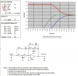
I need to substitute it in the linkwitz transform spreadsheet Q(0)
- attached
I also need an input for the desired Qtc/ Q(p). Is Q(p) = 0,707 ok?
Regards, Emil
- attached
How to get the actual Qtc of the simulated vented enclosure??
I need to substitute it in the linkwitz transform spreadsheet Q(0)
- attached
I also need an input for the desired Qtc/ Q(p). Is Q(p) = 0,707 ok?
Regards, Emil
Attachments
How can I adjust it to represent transfer function for a lower tuned vented box?
Excursion should not be issue, since the level of correction will be dependent on the volume:
- mcu volume control, LT/ whatever bass boost - applied as a 'dry/wet' mix to set the level of corection.
Excursion should not be issue, since the level of correction will be dependent on the volume:
- mcu volume control, LT/ whatever bass boost - applied as a 'dry/wet' mix to set the level of corection.
You can't.
For vented boxes, all you can do is use it like EQ. There is no "transformation" of the VB alignment or its parameters like what happens for a closed box, and the effect will be similar to using a low shelf type filter to boost the response but with the added bonus of being able to indepedently adjust the "shape" at the start (Qz) and end (Qp) of the boost curve.
For vented boxes, all you can do is use it like EQ. There is no "transformation" of the VB alignment or its parameters like what happens for a closed box, and the effect will be similar to using a low shelf type filter to boost the response but with the added bonus of being able to indepedently adjust the "shape" at the start (Qz) and end (Qp) of the boost curve.
Last edited:
Ok, so the shelving filter could have adjustable gain, right?
But I still consider dry/wet mix to adjust the level of correction (volume dependent, to avoid excursion issues).
If I adjust the gain - the more gain, the more phase shift?
If the boost filter is fixed gain, I could apply a phase shift (leading phase?) for the set gain, so I could have the shift flattened (as much as the phase shift circuit allows) for all levels set by the dry/wet mix?
Regards
Ok, so the shelving filter could have adjustable gain, right?
But I still consider dry/wet mix to adjust the level of correction (volume dependent, to avoid excursion issues).
If I adjust the gain - the more gain, the more phase shift?
Correct. Even if you do a mix and only partially apply some boost (of any kind) you will also be applying part of the phase of that boost as well. I am not sure why you would do a wet/dry mix to adjust the boost, when you can just adjust the boost level itself...

Also, the design of level-dependent circuits like limiters is not alltogether straightforward.
If you want to apply boost but no phase shift, then you should be using FIR DSP not analog filters.
If the boost filter is fixed gain, I could apply a phase shift (leading phase?) for the set gain, so I could have the shift flattened (as much as the phase shift circuit allows) for all levels set by the dry/wet mix?
I would not advise trying that kind of trick and I don't think it will work. The shape of the phase curve for LT or EQ is not the same as a "phase shift circuit" (e.g. allpass) so one cannot be used to correct the other.
I can simulate the circuits in series (low shelving/ all pass) to see the result phase shift.
I guess the result is the same, regardles the order (all pass before or after correction)?
What software can I use to simulate the enclosure, with the analog filters applied before?
I'd like to check the phase shift for the whole chain - including the groupd delay (phase shift) for the lower frequency.
Not sure how many cycles the phase shift + GD could be...
p.p.
- when the lowshelf filter is fixed gain, the phase shift is constant.
- when I mix it with unaltered signal, if the all pass has done some decent phase correction, isnt it goint be the same end result (good or not that good), regardles the mix level (altered/ unaltered signal ratio) ?
I recalled some stuff, looked at the phase shift plots for some filters and it is more or less useless to apply analog all pass phase shift.
All pass shifts phase uniformly for the whole spectrum, analog filters shift phase around/ above/ bellow knee frequencies.
----
The dry/ wet mix thing...
For simplicity, I plan to control the boost level with a series r2r matrix, giving (2^number of relays) steps. F.ex. 3 relays - 8 steps.
This way one can have a linear rheostat (not a potentiometer).
Linear rheostat might be used in a mixer circuit, or, regulating feedback in one opamp, first order shelving circuit.
If I have a more complex filter topology, requiring a pot, double pot, double rheostat to set the gain, I cannot do it with a minimum number of relays..
Last edited:
- Home
- Source & Line
- Analog Line Level
- Linkwitz transform calc