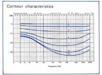
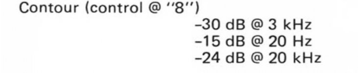
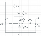
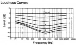
I'm going to build my own preamplifier. I plan to use a variable loudness function from Nakamichi 410 where the circuit is shown on attachment. The brochure exposed the characteristic curve as shown in attached as well. It said that the circuit reduced frequency of 3kHz to make the contour curve. I'm wondering that If I were to change the point to any frequencies, which parts should be varied and how much values? Are they only capacitors to be considered?
Attachments
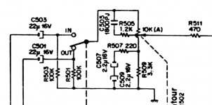
Capacitors and resistors both make that loudness curve.
Upper RC, above the wiper make treble boost, and lower, under wiper make bass boost.
Do you know how much values if I were to change the sagging point to 3.5kHz or at least the formula to calculate myself?
Do you know how much values if I were to change the sagging point to 3.5kHz or at least the formula to calculate myself?
Leave the resistors alone. Change the capacitor(s) bigger to shift frequency down, smaller to go up.
Leave the resistors alone. Change the capacitor(s) bigger to shift frequency down, smaller to go up.
This is similar to what I am thinking.
Could you or anybody derive the formula for the capacitor values?
Wow! amazing, could you tell me the equation to calculate the values, please? Or at least, help me if I were to use a 3,535.53 Hz as a center point.
Wow! amazing, could you tell me the equation to calculate the values, please? Or at least, help me if I were to use a 3,535.53 Hz as a center point.
The reason to choose 3,535.53 Hz was because found somewhere in a textbook suggested it. Sounds might be non-sense to somebody but I'm willing to try.
Anyone bumped into this circuit? I imagine a buffer before and after will do the trick. A couple of LM4562s should suffice.
I was planning on building one.
The Loudness Control, December 1963 Electronics World - RF Cafe
The methodoolgy of use will be as Yamaha instructed in the late 70s. Put the loudness into zero attenuation. Play the system at the max volume you are likely to play it. Perform all adjustments to bass treble. subs etc. at that level. When everything sounds fine, then attenuate from that level not using the volume control but the loudness attenuator.
I was planning on using a remote control motorized alps pot kit as the attenuator. This circuit would then sit just in front of the power amp.
Last edited:
From the article:
Do not be fooled by the uniform across-the-board treble rise of Fig. 1 from one curve to the other. It requires no compensation since it does not change at various levels.
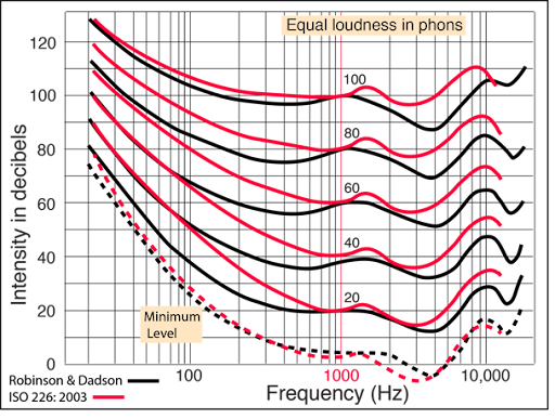
I’ve seen more than a few loudness controls that boost the high frequencies and this is wrong. Nothing about the Fletcher Munson curves or ISO 226:2003 indicates that this is necessary.
Please have a look on "Loudness Compensation, Use and Abuse" by Tomlinson Holman & Frank S. Kapmann, AES Preprint No. 1281 and/or US4220817A - Audio playback systems
- Google Patents
For correct adjustment with Nakamichi-like circuit there should be two controls: level and volume.
- Google Patents
For correct adjustment with Nakamichi-like circuit there should be two controls: level and volume.
Hi, I'd like to trouble all of you again.
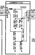
I wish to modify my Nakamichi TA-3 receiver's variable loudness. I found it's better to me with the old version in the older Nakamichi.
The old version was posted the circuit on the starting post. The newer version which I'd like to modify is on attached.
The different between them is the old one responses to 3 kHz, whereas the newer one responses to 1 kHz. But, the target point is 3.5 kHz.
Please help me.
PRR, could you help me again, please?
Attachments
Last edited:
I agree with Dimitri's comments.
Maybe old Yamaha schematics might be a good place to look.
Didn't they do the 2 control approach also?
Maybe old Yamaha schematics might be a good place to look.
Didn't they do the 2 control approach also?
Please have a look on "Loudness Compensation, Use and Abuse" by Tomlinson Holman & Frank S. Kapmann, AES Preprint No. 1281 and/or US4220817A - Audio playback systems
- Google Patents
For correct adjustment with Nakamichi-like circuit there should be two controls: level and volume.
- Home
- Source & Line
- Analog Line Level
- Variable Loudness modification