Due to delays in non-audio projects, I am, as they say, back on my BS.
I am putting together a PCB for a set of LR4 crossovers with a view to assembling a 2.1 computer-speaker set, with the fronts being two-way actively crossed over. Or you could think of it as a 3-way system with the LF channels mixed and run through a Linkwitz Transform.
If anyone with a clue has a few spare minutes, I would appreciate any input on the design as it progresses - it is on github. The files are for KiCad, but there's a PDF of the schematic which should be readable by anyone. I haven't started on layout for this board yet.
I will be getting a batch of blank boards made up in China and populating them by hand; reflow solder on a hotplate. Assuming they work, I may put the leftovers blank boards up for sale.
Some design assumptions, which people may or may not agree with:
Observant reviewers will immediately spot the, uh, inspiration drawn from Rod Elliot's (ESP) projects, for which I am extremely grateful.
I know we all love to hate on X7R caps in filters because of distortion and low effective capacitance when biased, but the classic rumble filter on a subwoofer has a bipolar electrolytic in series. Surely that has got to be worse than a big X7R being operated with approximately zero bias? Has anyone tested the difference? Or should I just make room for a 15mm KEMET film box-thing?
I am putting together a PCB for a set of LR4 crossovers with a view to assembling a 2.1 computer-speaker set, with the fronts being two-way actively crossed over. Or you could think of it as a 3-way system with the LF channels mixed and run through a Linkwitz Transform.
If anyone with a clue has a few spare minutes, I would appreciate any input on the design as it progresses - it is on github. The files are for KiCad, but there's a PDF of the schematic which should be readable by anyone. I haven't started on layout for this board yet.
I will be getting a batch of blank boards made up in China and populating them by hand; reflow solder on a hotplate. Assuming they work, I may put the leftovers blank boards up for sale.
Some design assumptions, which people may or may not agree with:
- gain control trimpots for each output
- most components are SMD for reasons of space, mostly 0805 because that's what I standardised on and have reels full of
- precision thin-film resistors where required in filters
- filter caps are SMD poly, so mostly 1206-1210
- C1/C3/R1/R3 in the Linkwitz Transform have multi-footprints to support creation of exact values
- supply bypass caps are X7R (small, cheap and good enough!)
- Linkwitz Transform caps are up around 1uF therefore through-hole
- opamps I hope to be DIP-socketed but will change to SOIC if I need the space
- aiming for max 100x100mm board to fit in the cheap proto PCB services
Observant reviewers will immediately spot the, uh, inspiration drawn from Rod Elliot's (ESP) projects, for which I am extremely grateful.
I know we all love to hate on X7R caps in filters because of distortion and low effective capacitance when biased, but the classic rumble filter on a subwoofer has a bipolar electrolytic in series. Surely that has got to be worse than a big X7R being operated with approximately zero bias? Has anyone tested the difference? Or should I just make room for a 15mm KEMET film box-thing?
Last edited:
New conundrum: I don't think I will get room corrections and things like the Linkwitz Transform correct on the first go. Should I put RC filter-packs on plugin daughterboards?
I was hoping to avoid goldplating and just have one single neat PCB... but "if you can't make it perfect, at least make it adjustable". Do I therefore also put the LR4 filter packs on daughterboards?
Any thoughts?
I was hoping to avoid goldplating and just have one single neat PCB... but "if you can't make it perfect, at least make it adjustable". Do I therefore also put the LR4 filter packs on daughterboards?
Any thoughts?
I know we all love to hate on X7R caps in filters because of distortion and low effective capacitance when biased, but the classic rumble filter on a subwoofer has a bipolar electrolytic in series. Surely that has got to be worse than a big X7R being operated with approximately zero bias? Has anyone tested the difference? Or should I just make room for a 15mm KEMET film box-thing?
Instead use Nichicon UES bipolar capacitors, much better.
https://www.nichicon.co.jp/english/products/pdfs/e-ues.pdf
Eh, it's still an electrolytic even if it's a fancy brand.
I re-did the subsonic filter as a single-pole 1.5u/6.7k filter for about 16Hz, wherein the R is the gain control pot for the LF output in parallel with 10k. That means I can use a sane-sized (though still through-hole ) film cap. Current schematic on github isn't quite right, but I'll put a new one up soon.
I re-did the subsonic filter as a single-pole 1.5u/6.7k filter for about 16Hz, wherein the R is the gain control pot for the LF output in parallel with 10k. That means I can use a sane-sized (though still through-hole
) film cap. Current schematic on github isn't quite right, but I'll put a new one up soon.Went on a similar adventure (2-way kind of generic crossover) but used discrete parts (BJTs, FETs).
Still haven´t looked at your github.
If I were to do such thing, I´d include high shelf, low shelf (for boost or baffle step), Linkwitz transform, notch filter and eventually delay correction.
If this is for one PCB only I´d probably buy a ready-made PCB for a 2-or 3-way XO but you probably won´t find anything with a Linkwitz transform.
If you could get away without LT, you could look at the TIDU035 from Texas instruments. They provide free gerbers for it. This one includes delay correction and baffle step correction.
(Analog Active Crossover PCB)
I mostly took inspiration from Linkwitz website (RIP!)
All you need is right there on one page:
Active Filters
There is even spreadsheets at the top of the page which makes designing the filters, LT etc. easy.
Just cascade all the filters you need.
If you include things like high shelf, low shelf, notches and thus stages you might not end up using, make them easy to "skip" with a 0R-resistor or wire.
Last edited:
X7R are the worst, electrolytics are way better:I know we all love to hate on X7R caps in filters because of distortion and low effective capacitance when biased, but the classic rumble filter on a subwoofer has a bipolar electrolytic in series. Surely that has got to be worse than a big X7R being operated with approximately zero bias? Has anyone tested the difference?
Cyril Bateman's Capacitor Sound articles | Linear Audio NL
The 100nF to 1µF article covers various high K ceramics and their truly abysmal performance. The 1µF electrolytic page covers bipolar and polar electrolytics.
(Its a big shame these detailed results don't have any systematic summary tables of results - I wonder if there's some more modern and systematic article with measurements of modern capacitors.)
OK I give up on the X7R thing - thanks As noted above, I managed to rearrange the subsonic filter to use a sanely-sized poly cap, so no need for 10uF anything.
My particular case shouldn't require all-pass time corrections or baffle-step compensation because of how the speakers are physically mounted, so I've just put some connectors in there as future-proofing to allow future daughterboards to be plugged in and provide those functions by intercepting the relevant signal chains.
github (incl PDF schematic) is updated now: showing signal taps, rejiggered subsonic filter, 10dB gain up-front for lower overall NF, and a buffered volume pot.
The feedback is appreciated
As noted above, I managed to rearrange the subsonic filter to use a sanely-sized poly cap, so no need for 10uF anything.My particular case shouldn't require all-pass time corrections or baffle-step compensation because of how the speakers are physically mounted, so I've just put some connectors in there as future-proofing to allow future daughterboards to be plugged in and provide those functions by intercepting the relevant signal chains.
github (incl PDF schematic) is updated now: showing signal taps, rejiggered subsonic filter, 10dB gain up-front for lower overall NF, and a buffered volume pot.
The feedback is appreciated
First of all, try to optimize the filter transfer function in such a way that the acoustic output of driver plus filter meets the desired target transfer function. Quite a formidable task in analogue. Rarely do we see- with the exception of DonVK- measurements of analogue active filter -driver combo's in the various DIYA threads.
After all that is done, you can choose premium components.
After all that is done, you can choose premium components.
I am not sure what you mean by "SMT poly" for the caps.
My investigations suggest PPS (polyphenylene sulfide) are good SMT option for filter caps, not quite as good as PP or PS but close, and better than PET.
PP melts at too low a temperature for surface mount.
The caps I was planning on using in most of the filters are Panasonic ECHU1C--G series, which are PPS and 2% tolerance. There's currently about 60 of them sitting in my farnell cart, and I tend to use lead/bismuth solder paste so I don't expect to overheat them in reflow.
https://industrial.panasonic.com/cdbs/www-data/pdf/RDI0000/ABD0000C173.pdf
The subsonic filter and larger caps in the Linkwitz Transform will be a plain old 5mm through-hole PET/MKT/MKP box kind of thing.
First of all, try to optimize the filter transfer function in such a way that the acoustic output of driver plus filter meets the desired target transfer function. Quite a formidable task in analogue. Rarely do we see- with the exception of DonVK- measurements of analogue active filter -driver combo's in the various DIYA threads.
After all that is done, you can choose premium components.
My crossover slopes are not very close to any driver misbehaviours or up against the limits of driver performance and are very steep, so I do not anticipate integration problems arising from driver behaviours. That expectation has been borne out using digital crossovers of the same topology with similar drivers. Room response and other stuff like 43" monitors getting in the way will be the killer, and frankly I will probably mostly ignore it until I can't.
Ain't nothing premium about this! I'm just trying to avoid some known pitfalls with material selection and make sure I didn't commit any unusually-dumb filter-design errors.
Last edited:
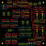
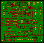
Progress is being made... I have placed and about half-routed the filter board.
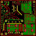
I moved all the power supply stuff to a separate board, which you can also find on github. It's a combination of linear regulated PSU to run the preamp stuff, plus a 12V switchmode brick for running control circuits (mute relays, fans, etc), and some logic to control the muting relays.
There are PDF schematic and PNG screenshots of the layouts of both boards in the github links for those without kicad, and a screenshot of the filter board partial layout is attached.
Attachments
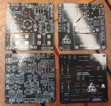
Prototype is assembled, bench-tested (signal generators and measuring voltage levels at various frequencies) and seems to be working, though it hasn't actually been plugged into any speakers as yet.
You can see the Linkwitz Transform section is basically unpopulated and there is a 4-pin header at the right which allows me to plug in a passive filter pack and experiment with different gains and shelving frequencies. I intend to tune that a bit using room measurements before committing to final values that are soldered to the board.
Similarly, the BSC, APF and Notch plugin sockets are bypassed with 0R. I could add filters on daughterboards to each of those in future if necessary but I suspect it will never happen.
PCBs for power amplifiers are due to arrive around the end of Dec; I should get onto machining up the cabinets in the next 3 weeks while I'm off work...
Looking good - bit of a mix of SMT and through-hole - I probably would have opted for SMT opamps, or socketed the through-hole ones (simply because you can if though-hole). What dielectric did you choose for the caps in the filter sections? I tend to go for PPS as they perform close to PP (which are not compatible with SMT due to the melting point).Prototype is assembled, bench-tested (signal generators and measuring voltage levels at various frequencies) and seems to be working, though it hasn't actually been plugged into any speakers as yet.
Yeah it's a "use up what's on my shelf" kind of design. Plan A was to use sockets (and to offload spare boards to like-minded nerds on diyaudio who tend to have stacks of spare DIP opamps), and I have heaps of sockets, but I couldn't find them until two days after I soldered it together
It's not like I'm some opamp-swapping mad-scientist, I have 40yo ears that DGAF about subtle differences of noise level between NE5532, TL072 or the goldplated stuff, so soldering them down is fine unless the design didn't work, which it did so that's all good! If I did it again, the opamps would be SOIC just to save me 10 minutes with the iron
Yes, the SMD filter caps are PPS; they are Panasonic ECHUX series in 2% tolerance. Resistors in the signal path are mostly thin-film metal, mostly 0.5%, except for where I've made up weird values in the linkwitz transform from multiple handpicked resistors from an eBay sampler book which may well be thick-film though they all measure better than 1% and have 4-digit codes. Who knows.
I wish KiCad had a similar concept for board layout as it does for nested sheets. As you can see here, there are multiple copies of distinct blocks (LR4 in Sallen-Key topology) which are easy to represent as schematic sub-sheets, but I had to lay out each one separately by hand
- Home
- Source & Line
- Analog Line Level
- (2x2).1 LR4+LT crossover system