This is a simple "yes" or "no" question, I guess.
Is the output of a standard variable-state filter 180% phase shifted in relation to the source? I've read that many phase shifts happen within the filter's integrators, but I don't know if the overall output is shifted as well.
I need to know this for a practical application and unfortunately my understanding is not enough to decipher it alone.
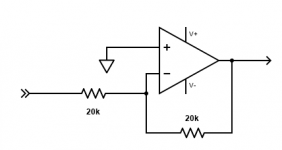
In the image you can find the exact circuitry I'm referring to.
Thanks!
Domingo
Is the output of a standard variable-state filter 180% phase shifted in relation to the source? I've read that many phase shifts happen within the filter's integrators, but I don't know if the overall output is shifted as well.
I need to know this for a practical application and unfortunately my understanding is not enough to decipher it alone.
In the image you can find the exact circuitry I'm referring to.
Thanks!
Domingo
Attachments
This circuit will be inverting. Some might say 180 degrees phase shift, but that is wrong.
The input polarity is inverted and this has nothing to do with phase shift. To preserve
the waveform, the phase response must be linear with frequency, not 180 degrees at all
frequencies.
The input polarity is inverted and this has nothing to do with phase shift. To preserve
the waveform, the phase response must be linear with frequency, not 180 degrees at all
frequencies.
Last edited:
Yes, a freebie.
If you build this, suggest that you use these parts for the electrolytics.
https://www.nichicon.co.jp/english/products/pdfs/e-es.pdf
If you build this, suggest that you use these parts for the electrolytics.
https://www.nichicon.co.jp/english/products/pdfs/e-es.pdf
Last edited:
>I've read that many phase shifts happen within the filter's integrators...
If the filter is setup for low pass and the frequency is above the pass band, it's gonna be attenuated and lag some. If the filter is high pass and the frequency is below the pass band, it's going to be attenuated and lead some. Same for the bandpass function; frequency on point, no phase lag or lead, below lead, above lag.
So of course there will be phase shift, just like in any filter. Depends on the filter function and the frequencies input and filter setup.
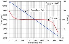
An integrator has a 90 degree phase shift throughout its useful range.
There also is a polarity inversion due to the circuit topology.
Op amps (open loop) pretty much do the same thing due to their internal compensation.
There also is a polarity inversion due to the circuit topology.
Op amps (open loop) pretty much do the same thing due to their internal compensation.
Attachments
Last edited:
Thank you for the answers, I'll try flipping the wires and if that doesn't work well(might affect the common ground for the other circuits?) I'll try with an inverted op-amp.
The reason why I ask this is because I want to be able to by bypass the filter gradually, using a simple mixer circuit between source and output. I know a simple switch would be more reasonable because gain might be different at output, but want to experiment.
BTW, I assembled the circuit for some time already and it does the magic, full control on equalisation and highly customisable. Using AD712's and MKS Wima caps at the moment. No added noise that I can perceive.
What would be the reason behind using Bipolar elcos @rayma? I'm using Nichicon ('gold') polarized at the moment.
Flipping the speaker wires is usually safe unless another component
is connected to the speaker wires.
However this won't help you, since you need a noninverting filter circuit.
That is, one with does not change the source polarity, so you can fade the
source out and the filtered version in (or vice versa).
Just add an inverting stage at the input of the filter circuit.
Are you using a bipolar power supply?
Those other caps will be ok too.
Attachments
Last edited:
Why do you need an op amp in the power supply? You can just use the batteries directly,
with one series pair per polarity. No virtual center tap is needed, since there's a real one available.
I'd also bypass the batteries with 100uF per series pair, but after the power switch so that any
capacitor leakage does not drain the batteries in storage.
Add the inverting stage before the input coupling capacitor. The source probably has an
output coupling capacitor, right?
Last edited:
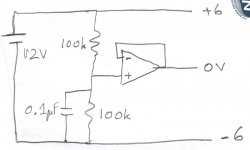
Sorry, sunday distraction ") . My power source is 3 x 3.6v 14500 lithium batteries, which splits into 5,4v+/- with the opamp. Right at the limit of the opamps minimum but this is for space reasons and because I'm powering in parallel electrets that are happy with the series at 10.8v. Attached goes the dual rail circuit in use. Should I increase the value of the by pass cap in your opinion? Or an extra 100uF be added on the positive pole, for example?
. My power source is 3 x 3.6v 14500 lithium batteries, which splits into 5,4v+/- with the opamp. Right at the limit of the opamps minimum but this is for space reasons and because I'm powering in parallel electrets that are happy with the series at 10.8v. Attached goes the dual rail circuit in use. Should I increase the value of the by pass cap in your opinion? Or an extra 100uF be added on the positive pole, for example?
Yes the source is a simple transistor CE preamp with an output cap. I'll include the inverting opamp in between as suggested.
. My power source is 3 x 3.6v 14500 lithium batteries, which splits into 5,4v+/- with the opamp. Right at the limit of the opamps minimum but this is for space reasons and because I'm powering in parallel electrets that are happy with the series at 10.8v. Attached goes the dual rail circuit in use. Should I increase the value of the by pass cap in your opinion? Or an extra 100uF be added on the positive pole, for example?Yes the source is a simple transistor CE preamp with an output cap. I'll include the inverting opamp in between as suggested.
Attachments
- Home
- Source & Line
- Analog Line Level
- Variable-state filter phase shift?