I need help with the controller for a motorized pot project from Elektor magazine. I is a project from 2008, and a basic description of the project, with links to pcb gerbers and controller software can be found here: Motorised Volume Pot | Elektor Magazine .
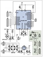
I used avrdude and a SparkFun pocket avr programmer to flash the RC5potm.hex file to the ATmega8 with apparent success, and then assembled the circuit on a proto board. It does not work. I have tried every Philips universal remote I own with every code I could find and get nothing. So, I did something wrong, but what? I am assuming that I have used the right file to flash the ATmege8 and have included the schematic.
I have never worked with a microprocessor before. Anyone have any suggestions?
George
Attachments
Hi George
I have no experience with that design but can offer a few things to try.
Check the output of the ir receiver with a digital scope. Capture the waveform and verify that the remote is sending out the correct protocol and the ir receiver captures it correctly.
Requires you to understand the protocol. From there you should be able to manually decode what was being sent to see if it matches what the software is to react too as far as address and command codes. Try this first
rsavas, and MAACO, thanks for your replies.
rsavas your suggestions, at this point, are a little over my head, so I’ll have to do more studying. One thing though, the IR receiver SFH5110-36 is obsolete so I used a VishayTSOP34536. Maybe that might be an issue.
MAACO, I didn’t do anything with the fuses. I used this command with avrdude: avrdude -c usbtiny -p m8 ATmege8 -U flash:w:RC5potm.hex
and got this result in this text file.
George
Attachments
I can't add much, but... try a different IR receiver? They can be salvaged from e-waste like DVD players, TV set-top boxes, wireless receivers for game controllers and stuff.
Is it possible there's an error with the schematic? It couldn't hurt to print out the Elektor board layout and compare it with the schematic and your prototype board (trace each connection with a coloured marker).
Or, try substituting an Arduino combined with a motor drive board (since running the motor directly from a bunch of paralleled microcontroller outputs seems risky). Cobbling together Arduino code to perform this function should be a cookbook exercise. It looks like you could program that Atmega8L with Arduino.
GitHub - MCUdude/MiniCore: Arduino hardware package for ATmega8, ATmega48, ATmega88, ATmega168, ATmega328 and ATmega328PB
Or, just getting Arduino to program a basic blinky sketch onto the microprocessor would give you confidence that you are programming it correctly. Add an LED and resistor to an appropriate output.
Last edited:
dangus, you make some good points. I’ve tried a few different IR receivers with no success. I have what is supposed to be a substitute for the SFH5110-36, a Sharp GP1UX310QS, coming and give it a try. I’ve imported the gerber files provided by the link in the thumbnail article into SprintLayout to study, and even used them and the PDF pattern provided to draw up my own pcb to have made if I got the circuit to work. I can’t find any references to schematic errors. Here is a link to the original article:
http://dr-shost.com/files/article.pdf
I do have a few tutorials bookmarked on some basic programming with the ATmega8, one with the flashing led. I’ll try to get that to work.
George
http://dr-shost.com/files/article.pdf
I do have a few tutorials bookmarked on some basic programming with the ATmega8, one with the flashing led. I’ll try to get that to work.
George
I made my own crude remote and wrote some code in bascom using a ATtiny part as a way to test out my receiver code. I chose the NEC code.
There is Atmel code available that displays the IR code type, on a character lcd, what is being sent too. Copyrighted material.
You have too many unknowns to solve, need a scope to at least figure out if the IR (HW) stuff is working to start with, maybe figure out what is being sent by the remote too.
MAACO, I didn’t do anything with the fuses
Atmegas have internal oscillators and can also be clocked with outboard ones.
Check in the documentation if You have to change the fuses since it could be being clocked internally.
Thanks dotneck335, I've seen Rod Elliot's circuit before. It's become a little bit of a challenge for me to see if I can get a micro controller working. I'm now looking at this project also:
IR Remote Controlled Motorized Potentiometer - Arduino Compatible - Electronics-Lab.com
IR Remote Controlled Motorized Potentiometer - Arduino Compatible - Electronics-Lab.com
This could be a job for an ESP32/ESP8266 "IoT" thing; it could be controlled both from IR commands and over WiFi so you can tell Alexa to turn up the volume. OTOH, if you have a WiFi IR bridge thingy already, that can control your amp volume plus any source units.
The Electronics-lab project should work with other Arduino-like things, and the motor controller chip could be replaced by a transistor h-bridge (like the ESP remote) or a pair of relays (same as controlling an aftermarket door lock actuator). I'd be tempted to add another relay for muting, and possibly another for source switching.
The Electronics-lab project should work with other Arduino-like things, and the motor controller chip could be replaced by a transistor h-bridge (like the ESP remote) or a pair of relays (same as controlling an aftermarket door lock actuator). I'd be tempted to add another relay for muting, and possibly another for source switching.
Last edited:
Your problem is most probably caused by the RC5 device code 17, tuner/amplifier, selected by Elektor.
RC5 code consists of device code identifying the type of device + the actual control code, see RC-5 - Wikipedia.
About all generic RC5 remotes are for TV and use RC5 device code 0 i.e. TV, and thus do not recognize commands with device code 17.
Elektor article tells that the codes can be freely can be freely
selected and changed. For this you need to change the table in buttons.c and recompile the firmware and program the controller again.
- Home
- Source & Line
- Analog Line Level
- Need help with a motorized pot controller