It is all guesswork without a circuit or having the unit in front of me I'm afraid but it is very odd for an adjustment like this to cause a resistor to burn if it is set incorrectly.
You could try and see where the resistor that burned goes i.e. what does that resistor do. Also see what parts the preset goes to. Could it be a current source/sink or perhaps?
You could try and see where the resistor that burned goes i.e. what does that resistor do. Also see what parts the preset goes to. Could it be a current source/sink or perhaps?
I accidentally burned 2 resistors because adjusting trimpots without care.
See post 33.
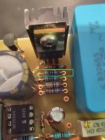
I will check where it's connected, this resistor in photo :
Very strange. I really don't without having it front of me.
I would still measure and record the DC voltage on all the 5534 output pins and then alter just one preset and see if any of the opamp outputs has altered at all.
Same for the supply pins.
Could the preset set a current in a discrete output buffer added after the opamps?
If that is so... and this is all just guessing... then I wonder if the resistor burned when the Bursons were in and that they caused it by suddenly drawing excess current because of running outside their max ratings. Thermal runaway in their discrete output stage.
That would be plausible if that was the timeline.
That would be plausible if that was the timeline.
The trim pots are for supply voltage adjustment only.
And where to measure voltage and what voltage to set? Should all trimpots adjusted to same voltage?
The supply voltage they have been set to originally.
In the first place I am not sure why you would want to mess with a beautiful amplifier.
Since there happened some destruction already and we do not know the full story (I
am sure) it is probably better to ask the designer.
Second thread for the same topic - only to confuse people and make things worse.
Single ended preamplifier bias
You already received good advice there.
As seen in post 36 the IC pins can be used as test points for supply voltages.
And here I talk about the amp ICs in the middle only, not about the regulator
ICs.
But on the other hand I see risk of a short if you check it at these pins.
It must be possible to find better test points, perhaps by using an ohmmeter.
With amp power off look where the output of the regulators connect to these pins.
Voltage measurement is with neg cable of the voltmeter to ground. I have no
idea where you got your numbers of "37.7V" , "36.6V" (post 29), "500mV"
(post 35) and 0.64V (post 41), what kind of measurement this was and how
and where you connected the test leads. Sorry, this is a complete waste of
time so far.
As said before a usual range of IC supply would be 15 .. 18 volts. The initial
setting was fine but can probably not be recreated. One trim for positive left,
next for negative left side etc. This means : plus say 15 volts on IC pin 7 with
respect to ground etc pp.
It seems you have access to the solder side of this amp board also, it would be
easy to take a good picture to confirm the style of regulators (suspected
"superreg" type). A better picture of the top side would help also, showing only
the essential area, between the big caps. Again, in the areas around heat sinks
are supply regulators.
Another pic is here : Single ended preamplifier bias
Remember we do not have this amp in front of us, have never seen it before,
we can not know what you did to destroy it and how the actual state is.
Besides we can not have any idea of your skills and tools.
- Home
- Source & Line
- Analog Line Level
- Trim pots on preamplifier circuit