Hi all,
I have set up my main monitors and I am in a bit of a bind as to the noise output. I think the culprit is the line-level analog crossovers, but I'm baffled by that, because those speakers and their electronics are supposed to be used in high-end studios, and that's definitely too much noise. The noise is white noise and it's mostly constant but fluctuates in loudness every now and then which would indicate to me either RF/EM pickup, or bad power supply capacitors. However, the thing has a grounded, steel, 1mm sheet box, so I don't necessarily think it's RF/EM pickup. The noise is put out via all transducers. It's the same loudness on both sides. I don't have an SPL meter capable of measuring this noise, but it's much too loud for room-level listening, to where it already gets tiring mid-day. I am a little more than 2m away from the speakers. Turning the power amp sensitivity on the rear panel down from 1V to 2V helps alleviate the issue (predictably the noise is 6dB lower), but it's still present. I perform main output attenuation in digital, before the DAC.
Do you think that based on my testing I am right to point to the crossovers as the culprit?
Is this sort of noise output to be expected from this level of equipment? (I list everything below)
How can I improve this without compromising monitoring quality?
A visual inspection of the insides of one (right) crossover revealed no obviously leaking or blown up capacitors; everything seems to be in order; the PCBs were signed off on 3.4.09, so I wouldn't expect there to be an issue here. Everything is very clean, but there's clearly a bunch of botching done at the factory due to the customization done for PMC.
I tested that the issue is at the crossover by doing the following:
1. Turn off left crossover - noise gone from left channel.
2. Turn on left crossover - noise back in left channel.
3. Turn off right crossover, disconnect cable from DAC going to crossover, short left channel pins 2 and 3 on the DAC end, and move the DAC and its associated cabling far away from the crossovers and amps - noise still present in left channel, no noise in right channel.
4. Restore the connections to their normal state; turn on both crossovers; unplug the cable feeding left HF from the left crossover to the HF stereo amp, unplugging it at the crossover - noise gone from left channel.
5. Plug the cable back in - noise back in left channel
6. The same tests provide the same results on the right channel
My electronics are as follows:
1. PMC MB2 XBD quad-amped main monitors, stereo
2. the standard electronics supplied by PMC for that, which are a customized version of Bryston SST2 electronics:
- PMC 10B crossovers. They are not the same as Bryston 10B. PMC 10B have main and LFE input and HF, MF, and LF output and all I/O is balanced XLR and there is no (front-panel) frequency adjustment; Bryston 10B have only line input and only split to HP and LP, have single-ended I/O, and allow frequency adjustment for each band using front panel rotary switches. Also note that the Bryston 10B is a stereo crossover (one box for both channels); the PMC 10B are mono crossovers, so you have to have two of them.
- PMC-branded Bryston 3B SST2 (stereo, 250W/channel), 4B SST2 (stereo, 500W/channel), and a pair of 7B SST2 amps (mono, 900W/channel). As far as I know those are exactly the same as Bryston, just with PMC branding. The 3B goes to HF, 4B to MF, and one 7B feeds LF and XLF to the left channel while another 7B feeds LF and XLF to the right channel.
- The XLR cables are 1m store bought ones, they're not amazing but they're fine. Two conductors + shield. I opened all the male plugs and cut the connection between the shield and pin 1 and insulated it with heat shrink, so now the shield is only connected on the female side.
- The crossovers are at the top of the stack, so they're pretty warm, but it's not like they're burning, they're merely warm to the touch.
Thanks
You are working very near field to the monitors and from your description of fault finding you are possibly hearing the noise floor of the crossover.
Solution: Turn down the gain of the power amplifiers until you can no longer hear the hiss, could be as much as -20dB. The crossovers will still have enough output to drive the amplifier to clipping with headroom to spare. This is the normal method for optimising signal to noise for professional audio
Given the vintage of the 10B it is possible that the op amps used internally could be up spec'd to quieter modern ones.
You could also be hearing the noise floor of components upstream to the crossover. It the system noisey with no inputs connected to the 10B?
There are settings in the 10B to increase or decrease input gain. You made need to make some adjustments for optimal signal levels.
Last edited:
The specs I found for the 10B crossovers say S/N ratio 90dB.
A good figure for an active crossover would be more like 115 to 120dB S/N ratio, if designed carefully (according to Doug Self).
So it sound like these crossovers might be rather poor performance.
90dB S/N at 0dBV is about 32µV rms, or 224nV/√Hz. Most good audio opamp stages are going to be somewhere in the 5 to 15nV/√Hz range for noise.
That 90 figure is possibly limited partially by mains hum of course, but still its rather indicative that the circuitry is not designed for low noise, which matches your experience.
The specs I found for the 10B crossovers say S/N ratio 90dB.
A good figure for an active crossover would be more like 115 to 120dB S/N ratio, if designed carefully (according to Doug Self).
So it sound like these crossovers might be rather poor performance.
90dB S/N at 0dBV is about 32µV rms, or 224nV/√Hz. Most good audio opamp stages are going to be somewhere in the 5 to 15nV/√Hz range for noise.
That 90 figure is possibly limited partially by mains hum of course, but still its rather indicative that the circuitry is not designed for low noise, which matches your experience.
Yeah but it shouldn't be bad. It's meant for mastering, and it's used at the top studios in the world, so why would it be noisy like that? I feel like it's performing less than it should, but I don't know really. I can't find any numbers for it. Did you find a 90dB figure somewhere?
The Bryston 10B is a very old design; it changed from discreet transistors to op amps during its production life. Things have moved on since then. 30 years ago when I ran a studio we never had ran power amps at full gain. As I said previously -20dB was a pretty standard gain setting for amplifiers to minimise noise. The 10B has +/- 24 volt rails so is probably capable of outputting +26dB into a 10kΩ load. Maybe the max output level is in the specs Mark found. There's some basic spec on Stereophile: Bryston 10B electronic crossover Specifications | Stereophile.com
The measured performance underwhelming by todays standards, at least for HiFi.
The measured performance underwhelming by todays standards, at least for HiFi.
Last edited:
I really like your idea of possibly upgrading the semiconductors. When I had a look inside I noticed some 5536's and what seemed to be discrete transistors, but they might as well have been voltage regulators. There might be some more things, there were daughter boards obscuring what's under them. But first I'd like to find out if my unit is just out of spec.
You mention attenuation. What do you suggest would be the best way to attenuate here? voltage divider on both hot and cold inside the xlr plugs? In-line attenuator like this hooked up on the output of the crossover?
JTS MA-123 – Thomann UK
You mention attenuation. What do you suggest would be the best way to attenuate here? voltage divider on both hot and cold inside the xlr plugs? In-line attenuator like this hooked up on the output of the crossover?
JTS MA-123 – Thomann UK
To optimise your signal gain structure you might need to add or remove gain and/or attenuate signals at each interface so each process is working at an optimal level for noise and headroom. The output of the crossover is apparently too hot to drive amplifiers with inputs rated at 1 or 2V, which is unsurprising if it can drive +26dB (~15 volts).
I think it unlikely to be out of spec. The noise specification isn't particularly good, you are driving amps at full gain (amplifying the noise floor of the crossover) and you are listening close to the speakers. What you hear is what I would expect you to hear.
Something between white and pink noise will be generated by all active stages. You say you have noise across all eight outputs. A single faulty/noisy op amp or transistor is not going to affect all outputs.
It is not impossible for a faulty power supply to inject noise, but I would expect that kind of fault would manifest differently in the different outputs because of the different circuitry for each section of the crossover.
Given the relationship between Bryston and PMC I am assuming that the PMC 10B is really a Bryson 10B with fixed frequencies to suit the PMC speakers.
The Bryston 10B has internal settings for gain structure. If the same is true for your 10B then the first thing is to check the most appropriate settings are selected for your signal path. Do you have any manuals or documentation from PMC for your crossover?
If there is no input attenuation available on the power amplifiers other than the 1V/2V switch you would need to make balanced attenuators to plug into the amplifier inputs. We used to make these to fit into a male / female XLR adapter. They are probably available off the shelf these days.
Attenuation at the last possible position in the signal chain attenuates all signal impurities collected along the chain up to the point of attenuation and at the amplifier is usually is the most appropriate place to put it. You just need to be sure that upstream gain settings are not amplifying noise unnecessarily before determining how much attenuation is needed at the amplifier.
Last edited:
I can't vouch for this company, but they seem to have dealers everywhere and they are not priced like hifi voodoo signal improvers.
Attenuators
If you used 10dB attenuators, you also have the 6dB available on the amps. 16dB should drop the noise to virtually inaudible and still allow 10dB of headroom in the crossover output drive capability.
Attenuators
If you used 10dB attenuators, you also have the 6dB available on the amps. 16dB should drop the noise to virtually inaudible and still allow 10dB of headroom in the crossover output drive capability.
Bryston erased all mention of the 10B from their website, but luckily they have archived their old website and the docs are here: 10B-STD Electronic Crossover - Bryston
My best guess is that internally the PMC 10B is a Bryston 10B LR, which is put in the "Three Way Mono" mode. You can read about it in the manual on that page. The brochure lists -90dB noise, but that's for the SST version, and mine is SST2, so I don't know if the spec might have changed.
I think the attenuators are 20-22k because that's what they measured for, not because there's a high pass filter inside. But if there is, then it looks like this thing can be opened up and gutted, and I have a soldering iron, so it shouldn't be much of a problem. Maybe I should buy one first and then go on with the rest.
Additional noise across all outputs could be added by one of two things:
1. noisy power regulation
2. bear in mind that each of those things is a series of low and high pass Linkwitz-Riley filters, so if the first gain stage or two are noisy, then everything is noisy.
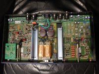
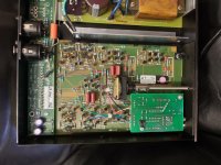
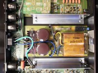
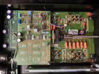
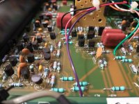
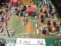
I'll upload pictures later, but I've written down all the semiconductors used in the PMC 10B.
The structure is as follows:
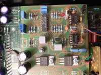
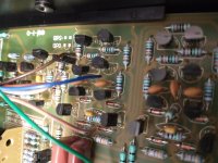
the basic structure of the stereo 10B is that it has a main power supply and then two large boards, marked L and R, which are used in parallel for the left and right channel. They have the same discrete filter structure built up 9 times on each board using transistors I list below, as well as ceramic capacitors, and some styrene capacitors as well.
This is then repurposed as stage 1 and 2 in the "LR" version which is put in "Three Way Mono" mode.
The "R" board has a small daughterboard on top which has its own power regulation and some op amps.
The "L" board has a small daughterboard with a discrete filter module which itself is an even smaller daughterboard again, and this is the only thing using SMD.
Parts:
Manufacturer logos:
(TI) - Texas Instruments
(N) - National Semiconductor
(ON) - ON Semiconductor
(f) - Fairchild
Op Amps:
Daughter board:
(TI) 67CRL3M
NE5534AP
(N) JR424AH
LF347N
Voltage regulators:
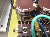
Main:
(ON) MC
7824CT
RAA846 G
(ON) MC
7924CT
RCE715 G
Daughter board:
(N) HM06AG
LM7915CT
(N)M75AL
LM340T15
7815 P+
Transistors:
(f)BJ16
PN100
A
(f)BJ17
PN100
A
(f)BJ40
PN200
A
(f)BH44
PN200
A
(f)BG51
2N
5400
(no marked logo)
2N
5550
-G47
SMD transistors on discrete filter module:
3M D
2Q 4
N1A 3
N2A 3
Diodes:
cannot make out
The structure is as follows:
the basic structure of the stereo 10B is that it has a main power supply and then two large boards, marked L and R, which are used in parallel for the left and right channel. They have the same discrete filter structure built up 9 times on each board using transistors I list below, as well as ceramic capacitors, and some styrene capacitors as well.
This is then repurposed as stage 1 and 2 in the "LR" version which is put in "Three Way Mono" mode.
The "R" board has a small daughterboard on top which has its own power regulation and some op amps.
The "L" board has a small daughterboard with a discrete filter module which itself is an even smaller daughterboard again, and this is the only thing using SMD.
Parts:
Manufacturer logos:
(TI) - Texas Instruments
(N) - National Semiconductor
(ON) - ON Semiconductor
(f) - Fairchild
Op Amps:
Daughter board:
(TI) 67CRL3M
NE5534AP
(N) JR424AH
LF347N
Voltage regulators:
Main:
(ON) MC
7824CT
RAA846 G
(ON) MC
7924CT
RCE715 G
Daughter board:
(N) HM06AG
LM7915CT
(N)M75AL
LM340T15
7815 P+
Transistors:
(f)BJ16
PN100
A
(f)BJ17
PN100
A
(f)BJ40
PN200
A
(f)BH44
PN200
A
(f)BG51
2N
5400
(no marked logo)
2N
5550
-G47
SMD transistors on discrete filter module:
3M D
2Q 4
N1A 3
N2A 3
Diodes:
cannot make out
I seriously doubt that the regulators are at fault, or would be the source of the noise in the outputs. With the setup as described there is possibly ~20dB too much gain. The output noise is rated at -90db but then you are adding ~30dB of gain in the amplifiers, bringing the noise floor up to just -60dB or so - you'd have to be deaf not to hear some noise.
The gain structure should be optimised before you start looking for faults. The Bryston 10B has a number of internal links for optimising gain structure; not sure about the PMC version. Even then you still need to pad the amplifier inputs.
The gain structure should be optimised before you start looking for faults. The Bryston 10B has a number of internal links for optimising gain structure; not sure about the PMC version. Even then you still need to pad the amplifier inputs.
Last edited:
I agree that padding would remove the noise to a good extent. However, the Bryston amps have way more headroom 90dB, and I'd like to get that if possible. What can I do to help this crossover achieve more headroom?
Regarding padding. You mention internal links in the Bryston 10B. Where can I find them? How do I set them? Thanks.
Regarding padding. You mention internal links in the Bryston 10B. Where can I find them? How do I set them? Thanks.
OK, so looking at the datasheets for the 7824C and 7924C (attached), I see the following specs:
7824C (+24V regulator):
Ripple rejection: 54 dB
Output noise 10 Hz...100 kHz: 10 uV/V_O (which I take to mean 240 uV at 24V)
7924C (-24V regulator):
Ripple rejection: 56 dB
Output noise 10 Hz...100 kHz: 170 uV at 24V (it's specified as a total unlike 7824C)
That's 410 uV / 48V = -101.3691543923506 dB.
That's only 12 dB less than the stated noise of -90dB. If every stage in the filter (8 transistors) just adds that amount of noise (my guess is it might be more) then just the 9 stages the HF goes through should easily hit -90dB noise. Would you agree with this?
One problem here is that there don't seem to be 24V 1A regulators with less than that amount of noise. There only seems to be this regulator from ON Semi and then the BA178 from ROHM which is 170 uV, which isn't that much better. What does one do to get lower noise on the voltage rails? I mean there are loads of devices there that are beyond the -90 dB or -102 dB barrier...
On the other hand, again exploring your gain staging suggestion, in a normal signal, the treble (which is the culprit here) will be anywhere near -50..-40 dB. So if I'm listening at -30 dB, then HF is at -80..-70 dB, which makes it noticeably close to -90 dB. So you're right that it's a good idea to stage the gain a little better. But I'd still like to explore whether it's possible to make the 10B's inherent noise lower.
Attachments
Regarding padding. You mention internal links in the Bryston 10B. Where can I find them? How do I set them? Thanks.
The schematics mention jumpers - they're already in the lower output setting on my units - is that what you meant by internal links? Thanks.
The output noise level from the regulators is not directly related to the noise level of the circuit that is supplied by those regulators; it depends on the circuit design. Typically a competently designed circuit will have ~60-100dB of rejection of power supply noise.
Also the amplifiers do not have more headroom than the crossover, they actually have much less. At an output of 0dBv the 10B has 26dB or more headroom but at 0dBv input the amplifiers have 0dB or 6dB of headroom depending on the input sensitivity setting. With a 20dB pad on the input of the amplifiers, it becomes 20dB or 26dB of headroom for a 0dBv input, which THEN more closely matches the headroom of the 10B.
Also the amplifiers do not have more headroom than the crossover, they actually have much less. At an output of 0dBv the 10B has 26dB or more headroom but at 0dBv input the amplifiers have 0dB or 6dB of headroom depending on the input sensitivity setting. With a 20dB pad on the input of the amplifiers, it becomes 20dB or 26dB of headroom for a 0dBv input, which THEN more closely matches the headroom of the 10B.
images inside 1
or go to PMC Bryston 10B Linkwitz-Riley Crossover Noise Issue + Inside/Teardown - Album on Imgur
or go to PMC Bryston 10B Linkwitz-Riley Crossover Noise Issue + Inside/Teardown - Album on Imgur
Attachments
-
 IMG_20210508_103740513_HDR.jpg1,014.1 KB · Views: 112
 -
 IMG_20210508_103812506_HDR.jpg823.2 KB · Views: 132
 -
 IMG_20210508_103834838.jpg906 KB · Views: 104
 -
 IMG_20210508_103844838_HDR.jpg810.6 KB · Views: 101
 -
 IMG_20210508_103908527.jpg815.4 KB · Views: 102
 -
 IMG_20210508_103921690_HDR.jpg579.8 KB · Views: 53
 -
 IMG_20210508_104005062.jpg809.5 KB · Views: 61
 -
 IMG_20210508_104105109.jpg935.5 KB · Views: 56
 -
 IMG_20210508_104158990.jpg817.7 KB · Views: 60
 -
 IMG_20210508_104212661.jpg809.8 KB · Views: 61
- Home
- Source & Line
- Analog Line Level
- High noise output from PMC Main Monitors due to Bryston Crossover