images inside 2
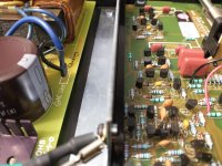
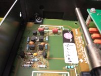
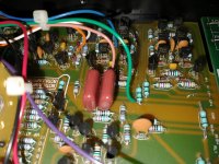
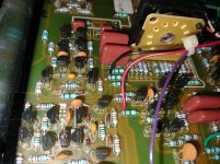
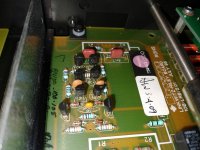
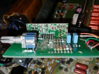
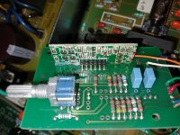
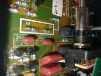
note that markings on the smd transistors are wrong (eg "3" replaced with ">") because apparently my phone's camera does some sort of AI upscaling that tries to read text.
note that markings on the smd transistors are wrong (eg "3" replaced with ">") because apparently my phone's camera does some sort of AI upscaling that tries to read text.
Attachments
-
 IMG_20210508_104222098.jpg807.7 KB · Views: 84
 -
 IMG_20210508_104233438.jpg698 KB · Views: 90
 -
 IMG_20210508_104310704.jpg912.4 KB · Views: 85
 -
 IMG_20210508_104318839.jpg991.2 KB · Views: 87
 -
 IMG_20210508_104336157.jpg852.1 KB · Views: 80
 -
 IMG_20210508_104456591.jpg845.1 KB · Views: 50
 -
 IMG_20210508_104516817.jpg830.6 KB · Views: 50
 -
 IMG_20210508_104732101.jpg746.8 KB · Views: 52
Bryston 10B Schematics - can also be obtained from archive org:
Bryston: 10B SCHEMATICS : Free Download, Borrow, and Streaming : Internet Archive
Bryston: 10B SCHEMATICS : Free Download, Borrow, and Streaming : Internet Archive
Attachments
The output noise level from the regulators is not directly related to the noise level of the circuit that is supplied by those regulators; it depends on the circuit design. Typically a competently designed circuit will have ~60-100dB of rejection of power supply noise.
The schematics only really show the discrete op amps running straight off the rails - there isn't any additional local decoupling or filtering in the schematic, and I would find it hard to find it on the photos of the board. Given that the op amps themselves are just 8 transistors each, there probably isn't much smart happening inside those either, but I'd be happy to hear otherwise. I don't know the first thing about discrete op amps. Would you say that there's less PSU noise rejection happening than the figure you mentioned above?
You are not comparing apples with apples. The Bryston's noise figure is measured below below 0dBv input, which is the input level for maximum power, AKA clipping. By comparison the 10B's noise figure below clipping it is ~90+26 = -116dB, much the same as the Bryston amplifier.
With a 20dB pad on the output of the 10B the noise figure will drop to -110 below 0dBv and the crossover will still have headroom when the Bryston clips. That is what optimising gain structure is all about.
Your problem is not noise in the crossover, your problem is too much gain after the crossover, amplifying the noise floor to make it audible.
The 5534 functional diagram shows 30 transistors, but this is only a simplified schematic. The OPA2604 is a much later design and probably has many more transistors that the 5534. Manufacturers don't want to show the actual guts in their op amps and give away trade secrets.
The noise from LM7*** regulators is a few tens of microvolts, or <-80dBv. The amount of noise in the supply that appears in the output of an op amp is lowered by its power supply noise rejection ratio. The 5534 specification for power supply noise rejection is 80dB minimum, 100 dB typical, the OPA2604 is 70dB minimum, 80 dB typical. In a properly implemented circuit the power supply noise in the output of the op amps is going to be <-80dB (noise of the regulator) minus <-70dB (noise rejection of the op amp) = <<-150dBv.
You are correct that the Bryston schematic does not show any power supply decoupling, however it is not uncommon for a schematic to leave those components out as they only clutter the drawing and make it more difficult to follow.
Last edited:
Turn the power amp all the way down. Note the hiss level. Sneak the power amp gain up until the hiss level *just* rises. Tape the gain knob so you don't mess with it.
You will have to turn-up somewhere else in your system to compensate. If you have way too many gain controls, repeat the above at each step from speaker to source.
You will have to turn-up somewhere else in your system to compensate. If you have way too many gain controls, repeat the above at each step from speaker to source.
If there is no decoupling on the board it is because none is needed, certainly not to improve the noise performance of the op amps.No, I mean look at the board, there isn't any decoupling visible either, or maybe I'm missing something, which is quite likely. The op amps used in the schematic are very simple, 8 transistors only.
Why do you think the op amps have only eight transistors? Did you not read my post above? High noise output from PMC Main Monitors due to Bryston Crossover
Last edited:
The op amps that are in the schematic are discrete. You can see the discrete transistors. There are eight per group. Either one group is one op amp, or two (they pair them in the schematic for the balanced version which this is). So one op amp is 8, or 4 transistors. I could see it either way. Just look at the photos.
Turn the power amp all the way down. Note the hiss level. Sneak the power amp gain up until the hiss level *just* rises. Tape the gain knob so you don't mess with it.
You will have to turn-up somewhere else in your system to compensate. If you have way too many gain controls, repeat the above at each step from speaker to source.
Thanks. That's gain staging. I get it. But right now I'm trying to improve the signal to noise ratio on the crossover.
We have been talking at cross purposes. I though you were talking about the 5532s and OPA2604s. All transistor amplifier circuits, even single transistor ones, have innate power supply noise rejection.
Put aside your preconceptions of noise generation and re-read the posts about gain structure and headroom (not just mine). Your system has too much gain after the crossover outputs, which is amplifying the noise floor. From your description is behaving exactly as would be expected.
You need to focus on the signal to noise ratio of the system and optimise the signal levels in each part. Then you can stop worrying about the crossover noise which won't be a problem.
Last edited:
...focus on the signal to noise ratio of the system....
Remembering that S/N is two parts: noise and signal.
If you are not peaking the signal in the Xover within a dB of clipping, you can get more Signal and thus more S/N.
Yes, some older gear sounds less-good in the upper 6dB even 10dB of its maximum output. But don't assume.
We have been talking at cross purposes. I though you were talking about the 5532s and OPA2604s. All transistor amplifier circuits, even single transistor ones, have innate power supply noise rejection.
Put aside your preconceptions of noise generation and re-read the posts about gain structure and headroom (not just mine). Your system has too much gain after the crossover outputs, which is amplifying the noise floor. From your description is behaving exactly as would be expected.
You need to focus on the signal to noise ratio of the system and optimise the signal levels in each part. Then you can stop worrying about the crossover noise which won't be a problem.
No I know what gain staging is, I just want to improve the crossover. That's why I started the thread. I know I can buy 20 dB pads and put them on the amp inputs. And in case I didn't know, the topic's been beaten to death already in this thread. But I'd like to talk about improving the crossover itself. So can we please talk about that instead of things everyone in the thread already knows...
You promised pictures; no pictures?
You say Bryston but then they are not the ordinary Brystons.
Halfway through you say the noise drops at times..... that's a MAJOR clue which only you can follow-up.
And in the end:
"Is this sort of noise output to be expected from this level of equipment?"
Possible. I used to turd-polish cassette and 4558-based gear. There's only so much you can do before it amounts to a rip-and-replace.
If you want the crossover quieter, try putting it in liquid nitrogen. If there was a silver bullet improvement to the crossover noise floor like you seem to be looking for Bryston would have done it already. They are very competent audio equipment designers.
Bryston specs for the current model are >+28dBv maximum output and -100dB unweighted noise. The spec for noise does not say whether it is dBm or dBv. If it is the more commonly quoted dBm then the total dynamic range is >130dB which is nudging theoretical limits.
Bryston specs for the current model are >+28dBv maximum output and -100dB unweighted noise. The spec for noise does not say whether it is dBm or dBv. If it is the more commonly quoted dBm then the total dynamic range is >130dB which is nudging theoretical limits.
Halfway through you say the noise drops at times..... that's a MAJOR clue which only you can follow-up.
That would be a fault. If it affects all outputs it can only be in the input stage preceding the crossover stages. If it affects one output only it will be in that section. Transistors and op amps can and do go intermittently noisy. A hot air gun and can of freezer spray might be helpful to find the faulty part.
Bryston specs for the current model are >+28dBv maximum output and -100dB unweighted noise. The spec for noise does not say whether it is dBm or dBv. If it is the more commonly quoted dBm then the total dynamic range is >130dB which is nudging theoretical limits.
Current model of 10B? They discontinued that. Where are you seeing those numbers?
My bad. The first numbers I saw were from stereophone and related to a 1995 model. The numbers from my last post from the user manual dated 2011 here:
http://old.bryston.com/PDF/Manuals/300001[10B].pdf
http://old.bryston.com/PDF/Manuals/300001[10B].pdf
- Home
- Source & Line
- Analog Line Level
- High noise output from PMC Main Monitors due to Bryston Crossover