Thanks! Couldn't have done it without you!
I recommend a wire connection to X6
Beautiful work!
Absolutely. Please do!
Is it o.k. if I add your photos to the documentation?
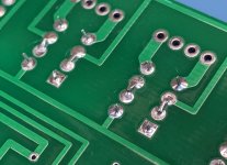
Oh, almost forgot. Don't forget to short the center pins on the input selector relays if your main board is a v1.0 and doesn't have the traces between them. As the documentation suggests, you can either jump them or bend the pins over and solder them together. I chose the bend-and-solder approach.
Attachments
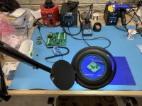
Yessir! It's a lifesaver machine! I bought a Yihua 948 desolder station, but it clogs up really quickly. So I just use it as a soldering station now and use the Hakko if I need to desolder anything. It's a power house.
Amazing work Chris!!! Is that a Hakko FR301 on the bench?
Thanks! Gotta tell ya, it's tiny. If you don't yet have a desktop magnifier, I highly recommend one. I couldn't have done this without one.
Dive in! The water's wet!
Dive in! The water's wet!
Amazing documentation and build work! Thank you. Makes me a bit less reluctant to get mine going. BTW - LOVE my FR301 too. I'm happy that I don't use it often, but when I do....
Attachments
LOL! I have a desktop magnifier for "normal" soldering, and I use a set of "jeweler's glasses" for SMD work or anything relatively tiny. No way I can do it without.
I am trying to decide which pre-amp I want to try it on first. I have a number of the boards and devices from the earlier version. I am leaning toward putting it on my ACP+, but I really like the "naked" look w/o the chassis. If I use the Muses... it really needs a chassis. Decisions, decisions. Both Iron Pres (Bal and SE) will eventually get the "Muses Treatment".
I am trying to decide which pre-amp I want to try it on first. I have a number of the boards and devices from the earlier version. I am leaning toward putting it on my ACP+, but I really like the "naked" look w/o the chassis. If I use the Muses... it really needs a chassis. Decisions, decisions. Both Iron Pres (Bal and SE) will eventually get the "Muses Treatment".
I have a special project coming up into which this will be installed. Details soon...
I am trying to decide which pre-amp I want to try it on first. I have a number of the boards and devices from the earlier version. I am leaning toward putting it on my ACP+, but I really like the "naked" look w/o the chassis. If I use the Muses... it really needs a chassis. Decisions, decisions. Both Iron Pres (Bal and SE) will eventually get the "Muses Treatment".
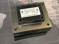
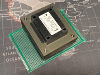
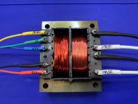
56VA 9V/36V (18Vx2) transformer came in today. Should make a fine source of AC for the volume control. Might even be a good choice for some other devices. I’ll mount it to a proto board, add some Euroblocks—instant power source. Not terribly beefy boards, but should be satisfactory until I want to build something purposeful.
DigiKey 595-1832-ND
DigiKey 595-1832-ND
Attachments
Last edited:
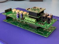
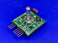
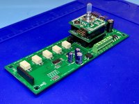
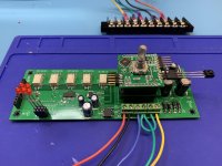
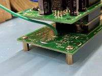
Got as far as I can today while waiting for the last couple of connectors and the rotary encoder to arrive. Got 'er packed and stacked. I had to desolder some connectors and replace them with Arduino-style stacked headers so that they could nest together. Another three cheers for the Hakko desoldering tool!
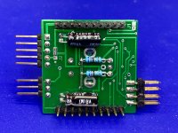
For those familiar with this setup, you'll notice that connectors X3, X4-3, and X4-4 aren't installed. These are the audio "integration points" depending on how you need or want to configure it. X3 is the place you can capture the audio after the attenuator and before the output jacks. Normally it's a 6-pin header with jumpers that connect the volume control to the output jacks (L/R/G or +/-/G). X4 is the place you can capture the audio after the input selector and before the attenuator. Since I'll be capturing the audio before the attenuator, I've left the X4-4 and X4-4 connectors out so I can wire directly into the board(s). I may still do something special with the audio after the attenuator with the X3 connectors. So I've left those connectors out of this set as well.
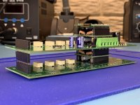
Looks a bit like a cargo ship!
For those familiar with this setup, you'll notice that connectors X3, X4-3, and X4-4 aren't installed. These are the audio "integration points" depending on how you need or want to configure it. X3 is the place you can capture the audio after the attenuator and before the output jacks. Normally it's a 6-pin header with jumpers that connect the volume control to the output jacks (L/R/G or +/-/G). X4 is the place you can capture the audio after the input selector and before the attenuator. Since I'll be capturing the audio before the attenuator, I've left the X4-4 and X4-4 connectors out so I can wire directly into the board(s). I may still do something special with the audio after the attenuator with the X3 connectors. So I've left those connectors out of this set as well.
Looks a bit like a cargo ship!
Attachments
Last edited:
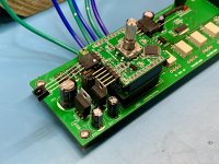
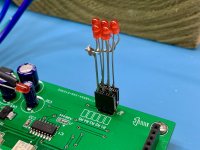
The remainder of the headers and the encoders arrived this weekend. Also installed the pair of pull-up resistors which are used to combat the cases where the micro won't wake up from its sleep state. This has been corrected in software, but I opted for the hardware approach for now.
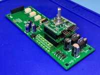
Ready to power up the unbalanced one and see how it works. Time to get a couple of temporary input/output pigtails on it, some status LEDs, the IR receiver chip, and get a transformer board fabbed up so I can give it some juice. I'll have that posted shortly.
Ready to power up the unbalanced one and see how it works. Time to get a couple of temporary input/output pigtails on it, some status LEDs, the IR receiver chip, and get a transformer board fabbed up so I can give it some juice. I'll have that posted shortly.
Attachments
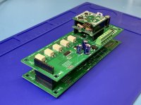
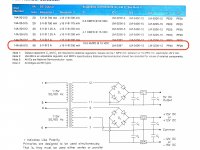
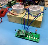
Got the 9/36V (9Vx1/18Vx2) transformer wired up and ready for testing. I checked the open-circuit voltage of the transformer after spooling up slowly on the variac and read about 11/20x2 which seemed appropriate. I connected it to the Muses stack and slowly brought up the voltage again and all was well. Measured the voltages on the regulators and was getting proper +/-15VDC and +5VDC. Then I heard sizzle sizzle, then smoked began emanating from the transformer and the 15V side ceased working. Well, I guess that was an underpowered transformer.
Double-checked the boards to make sure nothing was shorted. All the bridges and regs checked out good. Nothing shorted. I checked the spec sheet for the transformer, and while haven't spent an enormous amount of time noodling the problem, I can see that the sample regulator circuit that they show is slightly different from the way the Muses boards implement it. Muses boards have two separate rectifier sections, one for +15V and another for -15V. So it may have caused a low-resistance condition that the transformer couldn't tolerate. I'm not too worried about it. It was an inexpensive transformer that I thought might work given the wattage. I'll move up to a dual-wound Antec for the 18V side and use a separate single for the 9V side.
Never a dull moment! At least the Muses boards appear to be safe from damage.
Attachments
Last edited:
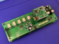
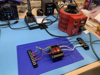
I received appropriate transformers this week and got a test jig set up so I can run through the functional checks of the Muses volume controls, both the balanced and unbalanced set. I'm using an 18VACx2 (for now--have a 15V on order) and a 9VACx2 toroid to provide AC for the onboard rectifier/regulators that create the +/-15VDC, +5VDC, and +3.3VDC. The regulators are good for 30VAC on the input, so no worries about over voltage with the 18V guy.
Neither of them will boot, which is odd. No blips, no blinks, no anything. I checked the DC rails on each, and one was down a -15VDC supply. I suspect that when the first transformer shorted, it probably took the regulator chip with it. The +15VDC rail was fine, and it drives the +3.3VDC regulator, so the processor should have booted. So I'll get a new -15VDC regulator on order to fix that problem and then do some more research as to why the CPU won't start.
Edit: After double-checking my rig, it seems as though there is no earth/audio ground when being fed by an AC source. Perhaps there's not a clean return path for the CPU to boot. I'm checking with the designer to see where an appropriate grounding location would be. There doesn't appear to be a dedicated spot on the main board for it.
Attachments
Last edited:
Good news! After re-reading the adjustment procedures, it turns out I’m just slightly blind and impatient.
The status LED is quite dim with the suggested 2K resistor, so I just hadn’t noticed it blinking at me. I watched closely as I powered up holding down the encoder button, and I also didn’t wait long enough for it to signal me. It works as expected and the remote control and parameter tables program as designed. So the micro is good! What a relief.
I still have a bad -15V regulator, and those are on order (or in transit from dB-Key - thanks dB!)
I’ll see what other features I can test with positive voltage only.
Oh, although it worked without it, I also provided a proper ground from my secondary main board on the balanced set since there were plenty of holes available from which to choose. We’ll see if it’s a noise generator and if I’ll need to move it closer to the power source entry point.
__________________
Attachments
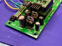
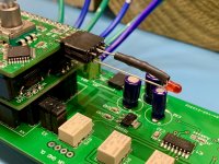
I replaced the damaged regulators tonight and now all rail voltages are correct. One of my uController boards is dragging the 3.3V line down to about 1.6V, so I must have a solder bridge somewhere. So I'll get that under the magnifier and see what I can see. When I take the uController board off of the stack, the 3.3V rail goes back to normal. So time for some sleuthing.
The other uController board is responding to IR programming, and I was able to set the device default properties for input connections, default input, and (un)balanced configuration. So I call that a success since the last post.
Next thing to figure out is why it's not triggering the input relays. Relay driver has voltage on the outputs (static high), so something needs to drive it low to trigger the relays and matching LEDs. Might be a connection problem with the serial data bus and/or clock since that's really the only thing that feeds it. Back under the magnifier.
Baby steps!
- Home
- Source & Line
- Analog Line Level
- Muses Electronic Volume Control Build from Wisconsin