A similar thread is at Audiogon, but would be interesting to hear from DIY audio members too
The emphasis is to improve the outlook of passive attenuators, to be far more appealing to audiophiles, so that their overall position is lifted considerably, enabling as priority best audio performance, but also not sacrificing nice needed features
A few being able to zero volume and have as many inputs as needed, contact less with both input switching and attenuation to start the ball rolling.
I use a preamp next to my armchair and have 10m RCA-cable to my active speakers.
this cable has 2000pF capacitance.
The amp has 22k input impedance, since this is in parallel with the gain pot, we have to choose a 25k to avoid too low input impedance.
When you listen at -6dB both sides have 12.5k, which makes 6.25k output impedance
this forms a low-pass of 12.7kHz (-3dB)
So a passive attenuator not a "preamp" will ruin the highs
Last edited:
The "Ultimate Passive Control " -- JLH,s 1980,s mosfet amplifier design with a 100K ohm variable resistor / potentiometer parallel with the input .
I have monoblock own build class "A" versions with outboard power supplies still working fine after nearly 40 years due to using quality components advised by JLH and a well know capacitor design engineer of EW fame.
I have monoblock own build class "A" versions with outboard power supplies still working fine after nearly 40 years due to using quality components advised by JLH and a well know capacitor design engineer of EW fame.
Not if your power amp matches its sensitivity to consumer line level. Consumer line level is nominal 310mvRMs, accordingly your power amp should be close to that same figure.
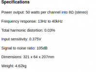
Here as example from a power amp manufacturer in business since 1936, the quad 306
providing sensitivity of 0.375mv
This takes some commitment to getting your gain structure right, with focus instead on your source. The benefit is you are no longer adding unnecessary reactance in between, and more likely to then hear what your source is actually capable of. Resistance being much more preferable than reactance, if we care about audio.
Attachments
My Hypex Fusion Amp FA503 requires 2.18Vrms at the RCA input.
Also if the power amp has to do the work of a preamp and make the additional 14-20dB gain, the noise level will rise, distortion too and bandwidth will be less.
I do not care how the inputs are selected, a normal Elna switch will do
but I want a headphone output with a separate fader
Also if the power amp has to do the work of a preamp and make the additional 14-20dB gain, the noise level will rise, distortion too and bandwidth will be less.
I do not care how the inputs are selected, a normal Elna switch will do
but I want a headphone output with a separate fader
Well you are stuck then with a power amp not having needed requirements.
Attaining correct gain structure does as I say take commitment to achieve, you can begin by finding a power amp, with similar sensitivity to consumer line level. You can then enjoy what your source component is actually capable of, by using resistance to attenuate its audio output.
Attaining correct gain structure does as I say take commitment to achieve, you can begin by finding a power amp, with similar sensitivity to consumer line level. You can then enjoy what your source component is actually capable of, by using resistance to attenuate its audio output.
However, even if you have a power amp with 400mV rms input sensitivity to full power, and you have sources that are all capable of at least 1V rms output, even though the gain structure will work for a passive attenuator, it still matters what the output impedance of your sources are, what the output impedance of your attenuator is, and what the input impedance of your power amp is... AND -- very importantly -- what the capacitance of your connector cable is.
What bansuri wrote previously is spot on. Even if the gain structure is all good, if you have high capacitance cable runs the passive attenuator can very easily degrade high frequency response... audibly. Let's look at an example:
- Let's say we have a pair of really cool powered speakers.
- Let's say those powered speakers have input impedance of 10k ohms.
- Let's say we choose a passive attenuator of 50k ohms.
- Let's say we need 5 feet of shielded cable running from our passive attenuator to each speaker (left and right).
- Let's say that cable has 150pF per foot capacitance (kind of high, but not crazy).
5 feet of cable at 150pF/ft = 750pF per cable
A 50k pot has a worst-case output impedance of 50k/4 = 12,500 ohms
Oh no! Our passive attenuator has far too high output impedance. We need an active buffer on that passive attenuator!
Let's say we use a 10k passive attenuator instead. The output impedance will be 2.5k, which is 1/4 the load impedance presented by the powered speakers. That should work.
The cable capacitance will create a low pass filter with the input impedance of the powered speakers. Rseries will be 2.5k and Cparallel will be 750pF.
The high frequency -3dB down point will be approximately 85kHz.
The high frequency -1dB down point will be roughly 42kHz.
That's good enough, but not with lots of extra bandwidth to spare.
If you have to use longer cable runs, the cable capacitances will go up. Let's say you need 10 feet of cable per side. Double the cable capacitance to 1500pF per side, from a 2.5k ohm source impedance. That will give you -3dB down at 42kHz, or -1dB at about 21kHz. While probably not audible, that is certainly not optimal. If, for instance, your phono preamp is -1dB at 20kHz, it will now be -2dB through that passive attenuator, which certainly could be audible if you're young and have really good high frequency hearing.
To get around this problem, one could reduce the value of the passive attenuator to only 5k ohms. Then the worst-case output impedance of the attenuator will be only 1250 ohms. But now all your sources will need very low output impedance so they can perform well into that low a load impedance.
What if you have this spiffy vacuum tube phono preamp that has an output impedance of 5k ohms? Well, now that preamp s going to be working into a 5k ohm load, which will make it pretty darn unhappy, distort, and reduce its output by -6dB. It will certainly not be working at as high a performance level as possible. That phono preamp will need a buffer on its output. (There we go again with those buffers...)
The moral of the story is that you really can't say any one value of passive attenuator is 'good' or 'bad'. This is all very system dependent. In an all-solid-state system with low source impedances, then you can use a low-value pot (10k or 5k) as a passive attenuator and get away with it. Add a vacuum tube component that doesn't have a buffered (low impedance) output and now you're in trouble.
None of the above had anything to do with gain structure, by the way. We're assuming that's all taken care of.
--
First off, resistive attenuators can be extremely good, if used *correctly*. The only differences between a resistive stepped attenuator and a very good log taper pot are the steps (pots are infinitely variable) and how well they track between channels.
Exactly what are today's requirements for a passive attenuator?
By moving beyond resistive attenuators, do you mean inductive attenuators? If so, why didn't you say so in the first place? That's a whole other kettle of fish, not to mention a whole other league of $$$ invested...
I have one of Dave Slagle's inductive attenuators hooked up between my sources and input selector and powered speakers. It works great (Thanks Dave!). But not all inductive attenuators are created equal. Dave put a lot of work into making that attenuator not overshoot on square waves. Put some inductive attenuators on an oscilloscope with a 10kHz square wave feeding them and you might be surprised at what you see...
--
Last edited:
If the Transformer Volume Control is correctly loaded by a representative
load impedance of say an amplifier and you can still see some overshoot
on a scope with a square wave the most likely reason is resonance above the audio frequency.
This is caused by the transformers leakage inductance resonating with its winding capacitances.
Typically this will be over 100Khz so not usually audible though it doesnt look nice on a scope.
If you want to remove it you can use a damping zobel on the o/p or use an AVC (autoformer volume control).
An AVC has an advantage in that its leakage inductance is lower so reducing the chances of resonances.
I believe the Intact Audio ones are AVC's.
When taking a look at your most recent threads, one can't help but notice that you seem to have an aversion against potentiometers that is not shared by too many other members. But hey, maybe start a third thread with the same lack of actual arguments.
100 years with the wrong purpose
Centenary Year of Invention of the Rheostat - Potentiometer
100 years with the wrong purpose
Centenary Year of Invention of the Rheostat - Potentiometer
I believe the Intact Audio ones are AVC's.
Yes, I think you are right.
What are the ramifications on impedance matching of using an autoformer as a volume control? Anything to worry about?
An autoformer works in the same way impedance wise as the separate primary/secondary style of transformer volume control but doesnt have galvanic isolation.
If your using either to attenuate, then its step down ratio determines the impedance transformation ie a 1:2 step down (-6db) means that the load impedance looks like x 4 to the source and the source impedance is divided by 4 when viewed from the load.
Of course if you were to try to get some gain by using a step up then the impedance transformation would work the other way which is not ideal.
Hope that answers you question.
knOppers. Im just explaining how AVC's and TVC's work so members can make up their own minds.
")
Yes I agree, rather what is needed is to escape the stupidity of using potentiometers passing audio signals as they are either linear or log, neither suit today's requirements as a passive.
if we move beyond that imposed restriction, things begin to look a lot better.
What????
I am afraid the strange belief about slider pots comes from the aversion against couple capacitors.
Now substantial offset is fed across the pot and electromigration will create surface pollution and crackling noises when moving the slider.
I hate stepped attenuators to adjust the volume, they serve their purpose in oscilloscopes, the sound is more fun to adjust with a smooth continuous slider which is properly implemented. 110-120dB of variable attenuation are possible.
Resistive optocouplers for audio level control have distortion--usually "medium " level .
I built one of the original design sine wave generators using "old school " optocoupling separate LEDS and receiver unit enclosed in a sealed from light enclosure .
I don't know how much the guy made out of his invention but he "disappeared" .
I built one of the original design sine wave generators using "old school " optocoupling separate LEDS and receiver unit enclosed in a sealed from light enclosure .
I don't know how much the guy made out of his invention but he "disappeared" .
- Home
- Source & Line
- Analog Line Level
- Desirable Features in Passive Preamps