Sorry in advance that this is a mish-mosh of questions. I added numerals to paragraphs to aid peoples responses.
The main subjects of inquiry surround these questions:
A:How do I pull power from pins two and three (48v and 0v) to create a symmetrical supply to juice an (in this case) op amp and bipolar transistors?
B:How do I protect the devices from phantom power?
So I've made a mic pre based on ESP P66. I had some questions which were answered after I posted about it in the forum
Mic pre Project 66 negative swing clipping
Now I have new inquires, although while these relate directly to this project, they're much more generally applicable concepts. I'm going to attempt to get them out as cogently as possible. Pretty much all “statements” should have question marks all over it.
1.I've sketched out most pertinent parts of all the circuits in here using www.falstad.com/circuit which I find to be a very helpful little app.
2. I might not even use phantom for this project, but I'd like to know how, and in any case being able to protect a device from phantom seems like a crucial ability.
Regarding phantom power in general Do all mixers provide the same amount of current? If the max power available is 48V/6,810Ω=0.007, so ~7mA, not a lot of power to work with. Does anyone know current draw for a variety of phantom powered devices? I recapped a CAD E200 recently, the active compliment in there is an OPA2107, a pair of TL062 and three TO-92 devices- it gets around the current limitation with two internal 9V NiMH. Shure SM81 has no additional power source with six active devices in it (a to-92 j-fet and five SOT23 BiPol transistors-a guess)
3. Generally speaking, the capacitors in series on the signal lines are there to block the DC, but not to protect the devices? The value of the cap determines low frequency roll off? Assuming “electrolytics in the signal path is sub-optimal” wouldn't film caps be a good choice (if their larger size can be managed)?
4.There are a number of schematics that incorporate diodes for what I gather are protection purposes, but the designs are all different. I can't find any clear and widely used schematic of phantom protection, and powering an op-amp/active device from phantom.
5.Some use Zeners, some small signal 4148/914, others 4XXX or I-don't-know-what.
6.The various orientations of the Zeners is particularly confusing to me- some have the "inside pair" cathodes directed to ground (FIG2A, FIG1), some pointed away (FIG6, FIG8)
7.I "understand" that the Zeners are clipping diodes, so for a 12V Zener, if a 15V (since the AC signal is riding along with the DC, do both AC and DC get "clipped"??) appears across a signal line and ground, the Zener will limit the voltage to ~12v.
8.ESP, which I usually find very informative is not elucidating anything for me. In FIG 3, are the op amps running off of +-12, provided from the 24V Zener D5 then split via the resistor divide R12/R13? D3 and D4- I have no idea what they're doing.
9.FIG 9 uses 1n914. Only protecting, not powering?
10.Fig 7 seems to be pulling power off the signal lines using 4 diodes(signal diodes?); powering but not protecting?. No idea how this works as drawn.
11.The only thing that makes sense to me is FIG 5 (my sketch). all 12V Zeners oriented the same way, power is drawn from “12+ and -12”, signal lines continue past the non-polar caps.
I could make this longer and longer, but hopefully I've revealed enough of my confusion that I can get help unraveling it. -->
--> -->
-->
One PDF I couldn't attach due to limit was TI “Phantom power with operational amplifiers”
https://www.ti.com/lit/an/sboa320a/sboa320a.pdf?ts=1614850698210&ref_url=https%253A%252F%252F
Much appreciated.
The main subjects of inquiry surround these questions:
A:How do I pull power from pins two and three (48v and 0v) to create a symmetrical supply to juice an (in this case) op amp and bipolar transistors?
B:How do I protect the devices from phantom power?
So I've made a mic pre based on ESP P66. I had some questions which were answered after I posted about it in the forum
Mic pre Project 66 negative swing clipping
Now I have new inquires, although while these relate directly to this project, they're much more generally applicable concepts. I'm going to attempt to get them out as cogently as possible. Pretty much all “statements” should have question marks all over it.
1.I've sketched out most pertinent parts of all the circuits in here using www.falstad.com/circuit which I find to be a very helpful little app.
2. I might not even use phantom for this project, but I'd like to know how, and in any case being able to protect a device from phantom seems like a crucial ability.
Regarding phantom power in general Do all mixers provide the same amount of current? If the max power available is 48V/6,810Ω=0.007, so ~7mA, not a lot of power to work with. Does anyone know current draw for a variety of phantom powered devices? I recapped a CAD E200 recently, the active compliment in there is an OPA2107, a pair of TL062 and three TO-92 devices- it gets around the current limitation with two internal 9V NiMH. Shure SM81 has no additional power source with six active devices in it (a to-92 j-fet and five SOT23 BiPol transistors-a guess)
3. Generally speaking, the capacitors in series on the signal lines are there to block the DC, but not to protect the devices? The value of the cap determines low frequency roll off? Assuming “electrolytics in the signal path is sub-optimal” wouldn't film caps be a good choice (if their larger size can be managed)?
4.There are a number of schematics that incorporate diodes for what I gather are protection purposes, but the designs are all different. I can't find any clear and widely used schematic of phantom protection, and powering an op-amp/active device from phantom.
5.Some use Zeners, some small signal 4148/914, others 4XXX or I-don't-know-what.
6.The various orientations of the Zeners is particularly confusing to me- some have the "inside pair" cathodes directed to ground (FIG2A, FIG1), some pointed away (FIG6, FIG8)
7.I "understand" that the Zeners are clipping diodes, so for a 12V Zener, if a 15V (since the AC signal is riding along with the DC, do both AC and DC get "clipped"??) appears across a signal line and ground, the Zener will limit the voltage to ~12v.
8.ESP, which I usually find very informative is not elucidating anything for me. In FIG 3, are the op amps running off of +-12, provided from the 24V Zener D5 then split via the resistor divide R12/R13? D3 and D4- I have no idea what they're doing.
9.FIG 9 uses 1n914. Only protecting, not powering?
10.Fig 7 seems to be pulling power off the signal lines using 4 diodes(signal diodes?); powering but not protecting?. No idea how this works as drawn.
11.The only thing that makes sense to me is FIG 5 (my sketch). all 12V Zeners oriented the same way, power is drawn from “12+ and -12”, signal lines continue past the non-polar caps.
I could make this longer and longer, but hopefully I've revealed enough of my confusion that I can get help unraveling it.
-->-->One PDF I couldn't attach due to limit was TI “Phantom power with operational amplifiers”
https://www.ti.com/lit/an/sboa320a/sboa320a.pdf?ts=1614850698210&ref_url=https%253A%252F%252F
Much appreciated.
Attachments
-
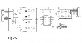 Fig 2a.jpg49.3 KB · Views: 45
 -
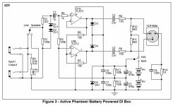 fig 3 active di ESP.jpg59.5 KB · Views: 46
 -
 Fig4.gif11.5 KB · Views: 40
 -
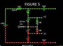 Fig 5.jpg30.6 KB · Views: 41
 -
 Fig 6.gif87.6 KB · Views: 44
 -
 Fig 7.gif45.8 KB · Views: 28
 -
 Fig 8.png29 KB · Views: 25
 -
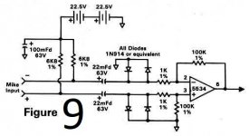 Fig 9.jpg32.4 KB · Views: 27
 -
 THAT mic pre phantom.jpg239.2 KB · Views: 27
 -
48V_Phantom_Menace.pdf152.9 KB · Views: 31
Last edited: