I'm not talking about 6L6's sketch.
(just scroll down a past the photos in post 1)
Yeah, I see it now. I was reading the schematic with the convention that a crossed wire is not connected unless there is a dot.
I think we are still talking at cross purposes or I am misunderstanding.
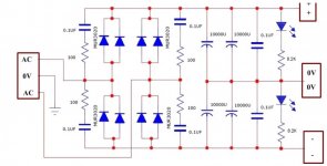
My power supply chassis has a fused IEC connector with the safety ground connected directly to the chassis. The hot and neutral leads connect to the transformer primary (actually through a soft start circuit - using the Neurochrome board). The transformer has four sets of double secondaries and one single secondary. Each of these feeds its own power supply board (with bridge rectifier, snubber circuit, and filter caps). So (except for the single rail ps) each has a positive, negative and common output connection.
The PCBs I'm using for each power supply board only has a single bridge so the two secondaries are connected to act like a center-tapped secondary and this is the common reference for each power supply. The basic schematic for each board is shown in the attached figure.
So, there are several ways this could be connected to the preamp chassis and ground.
1) All the common references connected together and then connected through a ground-break to the power supply chassis ground. The umbilical to the preamp chassis would then have a single ground connection.
2) Each of the common references connected through its own ground break to the power supply chassis ground, but kept as separate connections to the Preamp and connected to a star ground in the preamp chassis.
3) Each of the common references connected to the preamp chassis through separate connections. A separate connection from the preamp chassis star ground back to the power supply chassis and connected to the chassis ground through a ground break.
4) Same as 3, but with no connection to the power supply chassis ground.
Is there a better approach, or which of these is the preferred method?
Thanks,
Jay
Attachments
And Jim is Jim (6L6) and Wayne is Wayne. ;-)
Sorry I got all kinds of confused on this thread!
Anyways, Jay. Those power supply boards will be fine, but you won't have the advantage of separate secondary coils, treating the transformer as a center-tapped. Using separate bridges isolates the charging pulses better. It's not a huge deal though.
Are you using two separate preamp boards or one stereo board?
Yeah, I realize that having double bridges would be slightly better, but since I'm using the UltraBib shunt regulators in the preamp chassis, and they're being fed a much cleaner signal than they normally get from a direct transformer connection, I think they should work well enough.
My preamp will have two separate two-channel Salas DCG3 preamp boards, each operating as a balanced pair. Each of these boards will have its own UltraBib dual-rail regulator fed by one of the dual-rail supplies in the power supply chassis.
There will also be another two fully balanced input buffer boards that will each have their own Ultrabib regulators powered by the other set of power supplies. These buffers will feed a balanced Khozmo attenuator (e.g. four separate attenuator channels).
So everything is separate between channels and fully balanced.
btw - there are still separate secondaries for each power supply. A total of nine secondaries, treated as four center-tapped and one single rail. So I'm not sure what you mean by not getting the advantage of separate secondary coils. Is there further advantage by splitting the two rails on each PS (other than being able to use a full bridge per rail)?
Any recommendation on which of these four grounding approaches to use? I'd probably lean toward #3 unless there is something I'm missing.
Thanks,
Jay
Any recommendation on which of these four grounding approaches to use? I'd probably lean toward #3 unless there is something I'm missing.
Thanks,
Jay
In 3) as you describe it, you connect your power supply return in psu box via a cable that comes back from preamp box and then goes to your psu box chassis ground via loop breaker.
If you mean that in the psu you already have connected the returns to your chassis via loop breaker what the use of the extra cable from preamp box chassis to the psu box chassis via LB ?
So in 4) you eliminate this wire, right ? Kinda like what phono stage is suggesting, right ?
You better draw it or else we assume other things
You can have one loop breaker and separate each return (you have 4) with a resistor
Is your system all balanced ? What's your plan for single ended input ? (maybe I should ask this in the preamp thread)
OK, so I would treat each preamp board and it's power supply like a separate mono appliance. Actually use two earth-loop breakers.
This arrangement, x 2. This is from Rod Elliot's excellent article. The only difference is that you've got transformed AC going into the chassis, where this diagram shows active and neutral...
The only common signal ground these channels need between themselves comes from the patch cords. There might be some merit to tying the grounds together at the input panel.
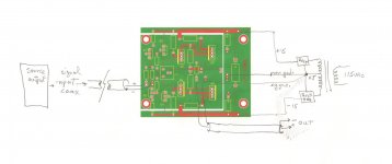
Your power transformer chassis should be earthed as usual, but there doesn't need to be any other connection between the two chassis. Actually, if you are using a shielded cable, the shield should be tied to earth ground so that it is an extension of the chassis. But it should only be connected on the transformer side, or a loop is created.
btw - there are still separate secondaries for each power supply. A total of nine secondaries, treated as four center-tapped and one single rail. So I'm not sure what you mean by not getting the advantage of separate secondary coils. Is there further advantage by splitting the two rails on each PS (other than being able to use a full bridge per rail)?
Thanks,
Jay
When you have separate coils and separate bridges, the transformers don't need to connect to a common ground bus between the filter capacitors. All currents are resolved in a short loop from bridge to capacitor and that's it. In a center-tapped arrangement, that common ground is also tasked with conducting charging pulses, and it gets a little noisy on that bus. Everything is referenced to this point anyways, and with full galvanic isolation between channels as you have, you'll have a quiet preamp. This is not like a huge phenomenon in respect to line level audio.
Thanks for all the feedback. Chris, that makes sense re separate coils and bridges.
I think I am going to go with option 2 and use a separate ground-break inside the power supply chassis for each power supply. I think I have enough room for this. I think I will also use the 15 pin connector on the power supply chassis so I can connect a cable shield to the chassis ground.
I think I am going to go with option 2 and use a separate ground-break inside the power supply chassis for each power supply. I think I have enough room for this. I think I will also use the 15 pin connector on the power supply chassis so I can connect a cable shield to the chassis ground.
I want to thank the contributors to this thread for their helpful advice and to Jaytor for bringing up this topic. Chris's link to Rod Elliot's treatise is most appreciated.
I have a more specific instance that perhaps needs more particular advice. Translation: I'm not sure I understand how to connect my grounds!
I'm trying to square the various advice of different experts -- Marshall W. Leach, Dick Marsh, Walt Jung, Jan Didden, John Curl in a unified build notion.
Specifically, taken together, the optimal features of a phono stage or preamp might include:
1. Keep channels separated to avoid crosstalk.
2. Power and signal sections in separate enclosures
3. Power and signal grounds and ground planes separate or separated on the board.
4. Separate transformer secondaries each feeding a dedicated bridge, rectification/smoothing, "super" regulation for each pole and channel (4 in total for a +/- supply)
5. Bring all grounds to a single point (star)
I've been playing around with PCB layouts for a Marsh line amp and Leach phono stage that locate the signal and power circuitry on separate boards. On the power boards keeping positive and negative grounds separate happens naturally which means that for each pole from secondary through to the load end the circuit floats independently. The opportunities for grounding seem to start at the boards but not finish at the PSU.
On the signal boards of these two projects, aside from the input and output wiring, there is just one ground connection point in the circuit. These three connection points can be made to the ground plane with that wired back to the ground post.
Marsh showed the signal and power grounds wired back to the power supply common but if there is no power supply common to, where should those ground returns connect?
My current thinking is that the signal and two power grounds meet at the ground post and a separate ground conductor runs back to a bridge in the power supply as described in Wayne's Pearl 2 article. Does that make sense? Or are these incompatible objectives?
And how does shielding and safety grounding work with the signal and power grounding that works for the above?
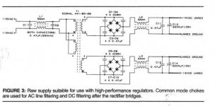
In summary I'm looking to use two of Gary Galo's Figure 3 supplies (I'm looking at the Triad FS...-C2 transformers) with boards like Marsh's and use Wayne's earth connection scheme... if that can work.
I have a more specific instance that perhaps needs more particular advice. Translation: I'm not sure I understand how to connect my grounds!
I'm trying to square the various advice of different experts -- Marshall W. Leach, Dick Marsh, Walt Jung, Jan Didden, John Curl in a unified build notion.
Specifically, taken together, the optimal features of a phono stage or preamp might include:
1. Keep channels separated to avoid crosstalk.
2. Power and signal sections in separate enclosures
3. Power and signal grounds and ground planes separate or separated on the board.
4. Separate transformer secondaries each feeding a dedicated bridge, rectification/smoothing, "super" regulation for each pole and channel (4 in total for a +/- supply)
5. Bring all grounds to a single point (star)
I've been playing around with PCB layouts for a Marsh line amp and Leach phono stage that locate the signal and power circuitry on separate boards. On the power boards keeping positive and negative grounds separate happens naturally which means that for each pole from secondary through to the load end the circuit floats independently. The opportunities for grounding seem to start at the boards but not finish at the PSU.
On the signal boards of these two projects, aside from the input and output wiring, there is just one ground connection point in the circuit. These three connection points can be made to the ground plane with that wired back to the ground post.
Marsh showed the signal and power grounds wired back to the power supply common but if there is no power supply common to, where should those ground returns connect?
My current thinking is that the signal and two power grounds meet at the ground post and a separate ground conductor runs back to a bridge in the power supply as described in Wayne's Pearl 2 article. Does that make sense? Or are these incompatible objectives?
And how does shielding and safety grounding work with the signal and power grounding that works for the above?
In summary I'm looking to use two of Gary Galo's Figure 3 supplies (I'm looking at the Triad FS...-C2 transformers) with boards like Marsh's and use Wayne's earth connection scheme... if that can work.
Attachments
- Status
- This old topic is closed. If you want to reopen this topic, contact a moderator using the "Report Post" button.
- Home
- Source & Line
- Analog Line Level
- Two chassis preamp grounding