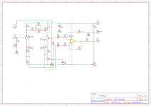
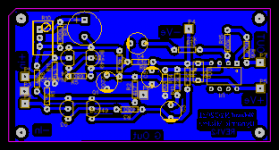
A while ago I built a P66 mic pre from ESP. Copied the schematic directly and did my layout in EasyEDA.
I don't have 2N4403 transistors so I'm using BC549 and BC559, both "C" type gain.
Testing it with a signal generator and a scope reveals that a portion of the negative swing is clipped- visually it's about a third of the negative swing.
Reducing the amplitude of the input signal doesn't help- the signal shrinks, but the portion of the signal that's clipped doesn't change.
altering the gain/attenuation pot on the board also doesn't cure the condition. Changing the frequency of the signal doesn't alter the clipping.
I pulled the transistors and verified they work. Their gains are also quite closely matched
I'm at a dead end. Anyone have any idea what's wrong or some advice?
Link to the original ESP project:
Low Noise Balanced Microphone Preamp
attached are images of my schematic (same as ESP P66) and PCB
Attachments
.....Testing it with a signal generator and a scope reveals that a portion of the negative swing is clipped- visually it's about a third of the negative swing.
Reducing the amplitude of the input signal doesn't help- the signal shrinks, but the portion of the signal that's clipped doesn't change....
This strongly suggests the signal generator has a problem which looks like clipping.
Can you post a waveform?
Check all the DC conditions before doing anything...
The opamp output should be near to zero volts DC.
The voltage on the emitters of the two PNP's will be about +650 millivolts.
The voltage at the junction of the 680/2200 resistors will be about one half of the negative rail value. For eg on -/+ 9v supplies you should see about - 4.5 to -5 volts. For -/+15 volt rails you would see -7 to -8 volts approximately.
of course. seemingly normal operation
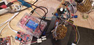
now the device works properly. I reinstalled the transistors into sockets and no clipping. I've had this thing built for a looong while now, this is it's first proper operation.
my signal generators have been working fine.my other DSO Oscope (top left of the frame) has some kinda issue, but my older one works fine.
now I just gotta case it, remote locate the pot, decide how I'll power it (perhaps some kinda phantom feed or a seperate PSU.) and maybe put a polarity switch in.Then give it to my father, who's when I talk about my ongoing projects and gear, been saying "you know what would be REALLY cool, is if you built a mic pre!"
I appreciate everyones input, because perhaps indirectly, you all got the device working properly.
Attachments

I am also building a microphone pre-amplifier, loosely based on Rod Elliott's mic pre design. I think you are missing a great part of the performance of this project by not using the 2N4403s or better---the best low-noise transistors for this application that I have found are the ZTX 450/550 pair. They are ideally suited for ~ 150 ohm mic source (like the typical Shure SM 57/58 found in nearly every recording studio in the world) according to "The Art of Electronics" by Horowitz-Hill. The other mod I did to his design was to lower the feedback resistors around the opamp---I cannot see any reason to use 100K/22K when 10K/2.2K will achieve the same gain at a lower noise point. By hand selecting the resistors in the complementary feedback pair differential input stage to match EXACTLY, I also think you can eliminate those 10uF caps. Just my 2¢.
Awesome feedback man. When I'm at my bench tomorrow I'll try swapping those resistors for the lower value. Less thermal noise.. of course! (*Eureka* lol). I'll have to put those ztx transistors on my next digikey order. Awesome that they're actually available too. Regarding dropping the 10uf caps- I don't understand their exact function. Is it DC blocking?
.... the feedback resistors around the opamp---I cannot see any reason to use 100K/22K when 10K/2.2K will achieve the same gain at a lower noise point. ...
Won't be the same gain unless the R10 et al network between the emitters is also scaled 1/10X. And that raises the distortion profile.
The 2-Q (or 4-Q) and one-opamp plan is all compromises. There's a $10 chip does much better.
Well, it's now closer to $7. Thanks for pointing it out. The INA217 is an impressive performer on the spec sheet in terms of noise (1.3nV/√Hz). Rod claims 1.9nV/√Hz, which is ~ 3 db worse, but fairly close. I am curious as to the huge difference between noise specs for the input and output sections---?? What's that all about? Wonder what the OVERALL noise is? Very good slew rate--15V/uSec. Not particularly stellar in THD, however; many opamps can beat their 0.004%. But probably below the threshold of perception anyway. At least the INA217 is still available in PDIP-8--that's good. Kind of a current hog, though--10 mA per opamp.
> noise specs for the input and output sections---??
At high gain, input hiss dominates.
At low gain, output stage hiss dominates.
I can't sort your decision tree for you. Is another zero of THD worth another buck? Or another mA? IMHO this performance was unattainable most of my life.
At high gain, input hiss dominates.
At low gain, output stage hiss dominates.
I can't sort your decision tree for you. Is another zero of THD worth another buck? Or another mA? IMHO this performance was unattainable most of my life.
"I can't sort your decision tree for you."
Nor would I want you to. Just asking for some friendly input.
"Is another zero of THD worth another buck?"
If you mean another order of magnitude, or -20db---yeah, it's probably worth a buck. But I do believe that distortion below, say, -100db, isn't audible to MY ears. The INA217 is at about -88db; so it may be audible. The good old standard is the LM4562 at -130, and they're only $1.65, or about 1/4th the cost of the INA217. It has more noise, though, and that's solved mostly by using the complementary feedback differential pair in front of it. And then it's still cheaper.
PRR- would the compromise you refer to be due to the fact that the discrete components are attempting to imitate the functionality of a self contained instrumentation amplifier?
For this project I'm going with separate transistors. I've got one instrumentation amp (AD620N) that I'm saving for a different project
Dotneck- how are you powering your project? Will the mic pre be in its own enclosure or a part of a larger system?
I'm having qualms over phantom power -both utilization (drawing from a mixers phantom feed to power the mic pre) and protection from (guarding against 48v when plugging any xlr cable into a phantom powered mixing board.) and am not finding satisfactory guidance, so I'm going to be starting a different thread.
I'd appreciate your input.
- Status
- This old topic is closed. If you want to reopen this topic, contact a moderator using the "Report Post" button.
- Home
- Source & Line
- Analog Line Level
- Mic pre Project 66 negative swing clipping