Hi forum friends,
My first post here. I hope this is the right section to post.
First some info on myself. I am a beginner in electronics repair equipped with a basic digital multimeter, a 40 watt soldering iron and an esr meter. Willing to learn more if someone can guide patiently.
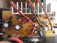
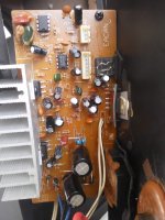
Last week when i switched on my pc to play some mp3 on this Sonic Gear speaker, i noticed the music is coming from two side satellite speakers but the bass(woofer) speaker no sound. Normally the bass will pump out some vibration. I fed dc3v to woofer speaker red and black wire at sp near cap c23, it had some speaker crackling sound. Fyi, the woofer speaker positive side is traced to 4th leg(output) of Tda2030 audio power amp at the bottom middle of img095833 while negative side is traced to yellow 104 cap at c27.
Using my dmm, i do voltage check at 8 pin op amp 4558 by positive red probe on pin 8 and negative black probe on center tap of transformer. Got 9.1vdc on both amp.
Another voltage check on tda2030, positive red to pin 5 and black negative to center tap transformer on all 3 pieces shown 15.7vdc.
I did 200ohm resistance test on those tda2030 by pin4 output to pin3 ground, the tda2030 near subwoofer speaker line showed 5.1 ohm.
Appreciate very much for anyone kind comment and suggestion on making the bass to come back again. Thank you in advance.
My first post here. I hope this is the right section to post.
First some info on myself. I am a beginner in electronics repair equipped with a basic digital multimeter, a 40 watt soldering iron and an esr meter. Willing to learn more if someone can guide patiently.
Last week when i switched on my pc to play some mp3 on this Sonic Gear speaker, i noticed the music is coming from two side satellite speakers but the bass(woofer) speaker no sound. Normally the bass will pump out some vibration. I fed dc3v to woofer speaker red and black wire at sp near cap c23, it had some speaker crackling sound. Fyi, the woofer speaker positive side is traced to 4th leg(output) of Tda2030 audio power amp at the bottom middle of img095833 while negative side is traced to yellow 104 cap at c27.
Using my dmm, i do voltage check at 8 pin op amp 4558 by positive red probe on pin 8 and negative black probe on center tap of transformer. Got 9.1vdc on both amp.
Another voltage check on tda2030, positive red to pin 5 and black negative to center tap transformer on all 3 pieces shown 15.7vdc.
I did 200ohm resistance test on those tda2030 by pin4 output to pin3 ground, the tda2030 near subwoofer speaker line showed 5.1 ohm.
Appreciate very much for anyone kind comment and suggestion on making the bass to come back again. Thank you in advance.
Attachments
i do voltage check at 8 pin op amp 4558 by positive red probe on pin 8 and negative black probe on center tap of transformer.
Op-amps usually work with symmetric supplies so Pin 4 should have the save but inverted Voltage -9.1VDC
You are reading speaker resistance for the ~8 Ohm woofer.the tda2030 near subwoofer speaker line showed 5.1 ohm.
Pin 3 should have inverted supply -15.7 like the op-amps.positive red to pin 5 and black negative to center tap transformer on all 3 pieces shown 15.7vdc.
Remove the woofer and check if it plays on another amp.
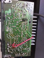
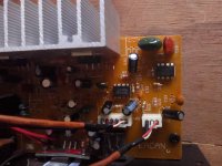
I would be looking at the solder pads on the second picture center left. (Subwoofer amp) I can also see a thin line above near the center. Check for PCB track interruption.
Hi Maaco,
Thank you for your reply.
Yes, my dmm shows inverted voltage -9.1vdc on Op-amp 4558 pin 4.
Yes, my dmm shows inverted supply -15.7vdc on tda 2030 pin 3.
Sorry i do not have another amp to play the woofer but i did connect it by wire to audio input from a walkman, and I can hear music from the woofer speaker.(refer img 110630)
Or do you have another better way of testing the woofer? Kindly advice.
From your comment, i rechecked and redo solder on center left of the woofer ic tda2030 and making sure all the pcb track has continuity.(refer img 102202). On the thin line above near the center, i think i clumsily scratched that line by accident. However, i rechecked the continuity of those 3 tracks affected but they are all ok and no breaking path was found.
Hope my feedback helps. Appreciate your comments and looking forward if there is any other testing that i can carry out.
Attachments
but i did connect it by wire to audio input from a walkman, and I can hear music from the woofer speaker.(refer img 110630)
So connecting walkman to amp input You get good sound, that means the amp is working.
Now follow the circuit back from that pin and You should find the fault.
There must be a place where the signals are summed.
Bad open resistor / capacitor or even those brown / black shielded connector wires where do they connect ? Pots ?
Right brown wire bass pot ? Short white & red to rule out the pot. I would be looking at the right op-amp since it's connected to it.
Remove the op-amps & solder sockets, so You can test them by swapping.
There is also a switching jack, but I presume it cuts both channels.
Last edited:
Refer img 073618 the pcb where i start checking resistor from top to bottom and found the following off the spec.of +-5%.
I listed the resistor label as per pcb, the actual value, then the read value from dmm.
R20=8.2k read 7.53k
R22=10k read 9.21k
R23=10k read 9.27k
R2=8.2k read 6.28k
R3=3.3k read 2.87k
R12=8.2k read 6.22k
R4=6.8k read 5.45k
R6=56 ohm read 81.7 ohm
R25=68 ohm read 94 ohm
R8=3.3 ohm read 0.5 ohm
R18=3.3 ohm read 0.5 ohm
R13=3.3k read 2.84k
R14=6.8k read 5.42k
R16=56 ohm read 81.9 ohm
Are the above resistors replacable by 1/4w 1% metal film resistor since the shop here sells only these type. Or else i might need to dig up my junk power supply to look for reusable resistor. Hope by replacing those resistor, the bass will come back.
Attachments
5% is within 20% spec, unless metal film were used which are usually 1%off the spec.of +-5%.
R20=8.2k read 7.53k ok
R22=10k read 9.21k ok
R23=10k read 9.27k ok
R2=8.2k read 6.28k suspect
R3=3.3k read 2.87k ok
R12=8.2k read 6.22k susp
R4=6.8k read 5.45k susp
R6=56 ohm read 81.7 ohm suspect ~double value
R25=68 ohm read 94 ohm susp
R8=3.3 ohm read 0.5 ohm (Shunt the leads and subtract this value from reading) but susp
R18=3.3 ohm read 0.5 ohm same
R13=3.3k read 2.84k ok
R14=6.8k read 5.42k susp
R16=56 ohm read 81.9 oh susp
You have to lift one leg, else You are measuring other components too.
Didn't answer
Right brown wire connects to bass pot ? Short white & red to rule out the pot.
I would be looking at the right op-amp since it's connected to it
Finger Touch connector pins. Bass reacting ?
Forgot to tell you that i measured all those resistors on board. I need to desolder and lift one leg of those resistors and remeasure for accuracy.
Refer to my first img 095833, the most right side brown wire consist of red, white and black wire connected to bass pot on the bass control knob. The white wire is connected to vcc pin 8 of op amp 4558 (the most right side one on img 095833).
You are saying about finger touch connector pin and asking if bass reacting. Which connector pin are you referring to? I had desolder one leg off resistor R6,R25,R8 and R16 and their resistance reading is as low as 0.01 or almost none. Is it still safe to switch on the power and do the finger touch like you mentioned? Any danger of the ic being burned of overcurrent?
The white wire is connected to vcc pin 8 of op amp 4558 (the most right side one on img 095833).
Seems to me pin 8 connects to the other op-amp by a jumper.
Pin8 It's the one near the green cap on top.
The shielded wire seems to connect to pin 2 input.
R10 seems broken. I see a solder blob in the hole.
8765
n n is notch
1234
Which connector pin are you referring to?
The white connectors. C21 C 2??? Input signals perhaps ?
R6,R25,R8 and R16 and their resistance reading is as low as 0.01 or almost none
Something isn't right. This can indeed explain a lot.
[/QUOTE]still safe to switch on the power and do the finger touch like you mentioned?/QUOTE]
I presume there is a transformer powering the PCB. So yes. Put the volume pots at midway.
Yes, pin 8 of op amp near the green cap connects to the other op-amp by a jumper.
I checked continuity of those shielded wire on both white connector vr1 and vr2 to input pin 2 of op amp near the green cap. There seems to be no continuity whatsoever. Is this the problem area we are getting soon?
While i checked the input pin 2 of the other middle op amp, it has continuity to vr2 white and black wires and vr1 red and black wire.
Resistor at R10 with color of yellow violet red gold is a 4.7k type, and it reads 4.11k on dmm. I had removed the surface solder blob in hole. Both the resistor leg was seated firmly on the pcb. Nothing broken. Refer img 095151.
The middle white connector vr1 is connected to input signal via a 3.5mm jack.
With main ac power on, i shorted bass pot white and red wire on the bass control knob and the volume pot turn to midway, then finger touch connector pin and i can hear some light hum noises from the woofer speaker.
Attachments
There seems to be no continuity whatsoever.
I believe there is a coupling capacitor in series..
The middle white connector vr1 is connected to input signal via a 3.5mm jack.
I presume signal in to volume pot & return. That explains 4 wires & two grounds.
Whites Inputs to pot & reds pot returns to first op-amp.
then finger touch connector pin and i can hear some light hum noises from the woofer speaker.
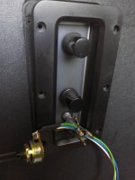
Ok, on the Bass volume pot You have 3 wires. The one in the middle is the wiper, so signal out to amp. On one side is input & then You have ground on the other side. Follow the wiper wire to the pcb disconnect pot & connect the walkman there. Do You hear strong bass ?
If Yes, the problem is before the pot or the pot itself.
If not, I would be swapping the rightmost op-amp
Hi,
You mentioned "Follow the wiper wire to the pcb disconnect pot & connect the walkman there." Sorry i am not sure how to connect the walkman input on the pcb . That is why i just disconnect the bass pot, replace with a 100k pot(B104 type as per img 084810) as i don't have stock of 50k pot.
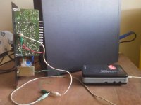
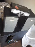
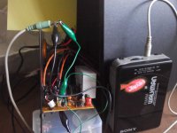
Connected the walkman jack to audio input as per my set up on img 104953.
There is normal audio from the two satellite speakers but nothing from bass speaker. Volume knob and treble knob is fully adjustable but there is no respond from adjusting the 100k bass pot. I am getting the same result as the original 50k pot.
Is this meaning the original 50k bass pot is still good? Off circuit i tested the resistance reads 48.8k ohm on 200k ohm scale.
Should i now proceed to put back the original 50k bass pot and install 2 pieces 8 pin socket for the 4558 op amp? So i can swap test the op amp anytime. Btw, i have not replaced any of the suspect open resistor. Also i remembered 4 of the resistors was desoldered on one leg and i haven't soldered it back to pcb as they are open and resistance are almost none. Will this affect or interrupt the bass output?
You mentioned "Follow the wiper wire to the pcb disconnect pot & connect the walkman there." Sorry i am not sure how to connect the walkman input on the pcb . That is why i just disconnect the bass pot, replace with a 100k pot(B104 type as per img 084810) as i don't have stock of 50k pot.
Connected the walkman jack to audio input as per my set up on img 104953.
There is normal audio from the two satellite speakers but nothing from bass speaker. Volume knob and treble knob is fully adjustable but there is no respond from adjusting the 100k bass pot. I am getting the same result as the original 50k pot.
Is this meaning the original 50k bass pot is still good? Off circuit i tested the resistance reads 48.8k ohm on 200k ohm scale.
Should i now proceed to put back the original 50k bass pot and install 2 pieces 8 pin socket for the 4558 op amp? So i can swap test the op amp anytime. Btw, i have not replaced any of the suspect open resistor. Also i remembered 4 of the resistors was desoldered on one leg and i haven't soldered it back to pcb as they are open and resistance are almost none. Will this affect or interrupt the bass output?
Attachments
Sorry i am not sure how to connect the walkman input on the pcb
It would be connecting the walkman output to the PCB pin where the blue wire (wiper) connects. If this works, it means Your problem is before the pot or the pot itself is bad.
You have to find out if the fault is before or after the pot. In the pre-amp / filter or in the Sub amp.
You could here also connect the wiper to another amp to find out if signal is reaching the pot.
Is this meaning the original 50k bass pot is still good?
Probably Yes, since the new one also doesn't work.
and i haven't soldered it back to pcb as they are open and resistance are almost none.
Open / broken resistors measure infinite. If they measure low resistance, they are shorted / burned, but they appear Ok on the pictures. Follow the color codes on them and replace if they don't correspond. Lower than a few Ohms doesn't make sense. Of course if they aren't soldered the circuit isn't complete & things don't work as they should. Perhaps You've found the fault already, but if they are low resistance that also means higher current flowing thru them & the 4558's could be been stressed. That's why I suggested changing the rightmost (Sub pot connected) op-amp. If it is also a 4558, Can't see by the pictures, any dual op-amp will do like NE5532, TL072 etc for testing. Replace resistors first.
There are meters which can measure resistors in place since the voltage is low enough to not activate semiconductor junction Voltage (>0.6V) My Fluke does that, but most don't. That's why You should lift one leg in order not to measure components in parallel with them which gives You incorrect readings.
It is hard to follow by pictures, I see solder pads on the underside , but don't see any wires or components at those supposed positions at the top PCB for example. Since there are few components, You could try to make a schematic and then follow it.
Last edited:
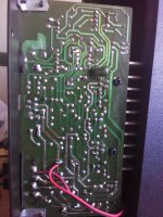
Connected the walkman output to pcb input red and black wire on vr2 as per my setup img 093117. I removed the vr2 shielded brown wire which connects to the 100k bass pot. I made sure i didn't connect or shorted to white wiper wire. Switched on mains but hear nothing, no sound at all. Is my testing setup done correctly?
But if i insert the 3.5mm jack into audio input, then there is audio from the 2 satellite speakers. Seems like the problem is somewhere after the bass pot.
Fyi, i have not replaced any of the resistors yet as the only electrical shop selling parts is not open due to the current covid pandemic. Also, i need to make sure which parts need replacement and then once the shop reopens, i will do the complete purchase.
Sorry to inform that i have no knowledge of drawing a schematic by tracing all the tracks on pcb.
Attachments
Fyi the 4 resistors that i had desoldered one leg off board are as follows:
R16 green,blue,brown,gold=560 ohm. Dmm reads 544 ohm
R8 orange,orange,gold,gold=3.3 ohm Dmm reads 104.4 ohm
R6 green,blue,brown,gold=560 ohm. Dmm reads 542 ohm
R25 blue,grey,brown,gold=680 ohm. Dmm reads 686 ohm
Funny to note that even though these 4 resistors were one leg off the pcb, the 2 satellite speakers are still working normal with adjustable volume and treble pot. Except the bass pot still no sound.
R8 orange,orange,gold,gold=3.3 ohm Dmm reads 104.4 ohm
Are sure about the colors ? 3.3 Ohm is a strange value. 100 Ohms is 100* higher. That could explain many things. Try looking with a magnifying glass or another light source. Sometimes Colors appear different. If it is really 3.3, short it to test.
i have no knowledge of drawing a schematic by tracing all the tracks on pcb.
I would ask a friend for help. As I told You it is a bit difficult this way.
You start with a pencil at the input for example and then draw the components following the tracks. At the end You have the schematic.
I can't determine by the pictures if the rightmost op-amp is indeed a 4558. Could be a single op-amp like a TL071. The pot seems to connect to pin2 but the supply pins are different between the two. Sorry I can't help more.
MAACO,
Thank you for helping me up to this stage, although is is sad to hear you can' t help more.
It has been an enriching insight and learning experience into the area of subwoofer. Btw, the rightmost op amp and the middle one are 4558 type. I will get the 8 pin socket too.
Hope that the shop selling electronic parts will open by next month and i most likely will go buy those needed parts.
Best of wishes to you.
- Status
- This old topic is closed. If you want to reopen this topic, contact a moderator using the "Report Post" button.
- Home
- Source & Line
- Analog Line Level
- Help diagnose Sonic Gear 2.1 woofer no bass