Hi there,
is there a basic circuitry that completely eliminates a line level output transformer and behaves exactly like this, i.e. keeps the differential output level constant regardless whether one of both terminals is grounded or not? Quasi the opposite of an instrumentation amplifier consisting of three opamps...
Best regards!
Is your receiver converting to unbalanced? If yes, then you can float both lines in quasi-balanced configuration. You lose the voltage gain coming off a differentially driven output, but do get the benefit of noise rejection.
TI and THAT make line drivers that mimic transformer balanced operation. The venerable DRV134 would be one of them, though the newer LME49724 are significantly better.
TI and THAT make line drivers that mimic transformer balanced operation. The venerable DRV134 would be one of them, though the newer LME49724 are significantly better.
If opamps are enough to drive the load, then schematic 3A in this works very well.Balanced Transmitter and Receiver II
There is also this one for true differential function Project 176 but Zin is low and then again why not something like that https://www.ti.com/lit/ds/symlink/opa1632.pdf?ts=1605257314082&ref_url=https%253A%252F%252Fwww.google.com%252F
There is also this one for true differential function Project 176 but Zin is low and then again why not something like that https://www.ti.com/lit/ds/symlink/opa1632.pdf?ts=1605257314082&ref_url=https%253A%252F%252Fwww.google.com%252F
Are you asking about an output that is balanced being able to have one side shorted to connect to single ended? My focusrite has outputs like that but the distortion performance goes out the window when you use a TR plug instead of a TRS.
I actually made up circuits to convert balanced to SE and SE to balanced to get around that issue with the distortion increasing (it is not subtle) when doing measurements.
edit: sorry I'm a bit confused because the subject seemed to be the opposite and I started to answer with my circuit for doing unbalanced to balanced, but then stopped.")
Tony.
I actually made up circuits to convert balanced to SE and SE to balanced to get around that issue with the distortion increasing (it is not subtle) when doing measurements.
edit: sorry I'm a bit confused because the subject seemed to be the opposite and I started to answer with my circuit for doing unbalanced to balanced, but then stopped.
Tony.
Last edited:
There is much reliable documentation on why OP-amps and discrete are very hard to balance perfectly enough to be of any real benefit. On a single chip, they can match things better.
Have you started by reading all of the Jensen white papers? Yes, it is about transformers, but it is about the problem.
I'll look into the new TI chip. That would be a flip from last time when THAT beat TI. Things progress!
Have you started by reading all of the Jensen white papers? Yes, it is about transformers, but it is about the problem.
I'll look into the new TI chip. That would be a flip from last time when THAT beat TI. Things progress!
Those opa1632's that MagicBus posted seemed to be the best thing around when I was investigating, but the SMD put me off. That lead me to do something simple with lm4562's. I unfortunately have never got past the breadboard stage though.
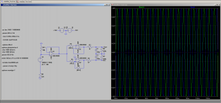
This is what I was working on today (revisiting the sim) I need to get my measurement setup working properly before I tackle some mods on my main amplifier.
This is something I was working on to take SE output from a line stage or amplifier and feed into the balanced input of my focusrite 2i2 (with appropriate attenuation if from an amp). Low noise and low distortion being the two primary goals.
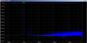
I'm using LM4562's. obviously the simmed distortion and noise floor is completely unrealistic, but I'm hoping for better than -120db noise floor and I the distortion should be well below the focusrites capabilities (probably better than 0.0001%).
Still not sure if this is the sort of thing you are after.... Just what I came up with after looking at some of the other things like Rod's circuits, where I wanted something as simple as possible, but still gets the job done
edit: oh and to tvrgeeks point, you will need 0.1% resistors to get even close to the dedicated chips as far as noise rejection is concerned. In my case the That's just didn't cut it (from what I could see from the datasheets) from a noise floor perspective (aiming at getting as close to 140db noise floor as possible).
Tony.
This is what I was working on today (revisiting the sim) I need to get my measurement setup working properly before I tackle some mods on my main amplifier.
This is something I was working on to take SE output from a line stage or amplifier and feed into the balanced input of my focusrite 2i2 (with appropriate attenuation if from an amp). Low noise and low distortion being the two primary goals.
I'm using LM4562's. obviously the simmed distortion and noise floor is completely unrealistic, but I'm hoping for better than -120db noise floor and I the distortion should be well below the focusrites capabilities (probably better than 0.0001%).
Still not sure if this is the sort of thing you are after.... Just what I came up with after looking at some of the other things like Rod's circuits, where I wanted something as simple as possible, but still gets the job done
edit: oh and to tvrgeeks point, you will need 0.1% resistors to get even close to the dedicated chips as far as noise rejection is concerned. In my case the That's just didn't cut it (from what I could see from the datasheets) from a noise floor perspective (aiming at getting as close to 140db noise floor as possible).
Tony.
Attachments
Last edited:
If opamps are enough to drive the load, then schematic 3A in this works very well.Balanced Transmitter and Receiver II
Figure 3 does what Kay asked for, but 3A does not: the output level halves when you short one output to ground. The same holds for wintermute's schematic.
SMD unfortunately is a fact of life when we are talking -140dB and .000-something. Parasitic factors rule in that domain. We are pushing current engineering limits* and close to the Johnson noise limits. Damn laws of physics.
Some assessment if "good enough" needs to come to play. I suggest a more broad system approach. Solve the first 90% of your biggest problem and move on to the next. In theory, that last 10% may eventually be the biggest problem and you can address it then if you can afford to. Is there any advantage in my new DAC measuring .0003% HD when the recording passed through probably hundreds of NE5534's or worse in the studio? Are we expecting balanced interconnects to magically fix a basic internal box grounding scheme problem? Money spent to go balanced when everything is within a meter of everything else? Mics on the stage and mixers 100 feet away is an entirely different problem of course. Are the problems really from Florescent or LED lights? Gad can some of the LED lights put out RF crap. If I was building a studio, it would be all incandescent and not a dimmer in the building. How many amps have you seen with balanced IO, but the transformer is not in a mu-metal pot?
* I worked on circuits where inductors, transformers, and capacitors were implemented by the board foil. Every land had to be treated as a transmission line. And that was 35 years ago!
I'm coming around to using smd, but my biggest obstacle is that I'm not so confident and like to breadboard stuff till I get something I'm happy with. That's something I can't do with SMD also in my context, I'm trying to make something for measurements, and I want to keep as much of the native performance of the eventual input device as I can, yes for other "normal" applications the 100+ db performance of the That or DRV chips should be more than adequate
Tony.
also in my context, I'm trying to make something for measurements, and I want to keep as much of the native performance of the eventual input device as I can, yes for other "normal" applications the 100+ db performance of the That or DRV chips should be more than adequate Tony.
Last edited:
SMDs are definitely less convenient when you want to use a breadboard or a perfboard, but there are adapter boards, SO ICs can be soldered to a piece of perfboard using thin wires and 1206 or 0805 passive components more or less fit between two copper islands of a perfboard with 2.54 mm (0.1 in) grid.
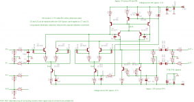
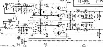
I've attached a schematic of the single ended to balanced output circuitry commonly used in Otari tape decks, note that this design maintains a constant output voltage in balanced or unbalanced output connections.
You can simplify by eliminating the buffer transistors and bias circuitry.
Normally I would draw something up, and post so my apologies for the obscure post - just not a lot of energy on tap right at the moment.
Anyone using THAT corp balanced input receivers I strongly recommend you add zener clamps and current limiting resistors on the inputs. Don't ask me how I know but it was a pretty unhappy experience. They're excellent devices but can be destroyed despite their relatively robust specifications.
Attachments
Hi there,
is there a basic circuitry that completely eliminates a line level output transformer and behaves exactly like this, i.e. keeps the differential output level constant regardless whether one of both terminals is grounded or not? Quasi the opposite of an instrumentation amplifier consisting of three opamps...
Best regards!
Analog Devices SSM2141, T.I. INA134, aforementioned THAT 1240
THAT Corporation 1240-series Balanced Line Receiver ICs
https://www.ti.com/lit/ds/symlink/ina134.pdf?ts=1605276557183
https://www.analog.com/media/en/technical-documentation/data-sheets/SSM2141.pdf
I'm partial to Analog Devices but they are all excellent. They were commonly used in broadcast gear in years past.
Keep in mind these are laser trimmed during manufacture. You'll have a hard time getting that level of
performance with discretes without a lot of work.
G²
Last edited:
Analog Devices SSM2141, T.I. INA134, aforementioned THAT 1240
THAT Corporation 1240-series Balanced Line Receiver ICs
Don't you mean THAT 1606/1646? The 1240 is a receiver rather than a driver.
THAT Corporation 1606/1646 OutSmarts Balanced Line Driver ICs
Thanks, Tony, these basically are my considerations, too. I'm not an EE, (audio) electronics just is an amazing hobby for me. Hence, trying to achieve a certain goal with discrete components offers some valuable educational aspect to me. I just wanna see what's going on or what has to be done here. It's by far more than wiring of THAT or whatever chips according to their datasheets which just resembles painting by numbers. To put it clearly, I duely respect that THAT or TI or ... chips most certainly will lead to better results.I'm coming around to using smd, but my biggest obstacle is that I'm not so confident and like to breadboard stuff till I get something I'm happy with. That's something I can't do with SMD
Best regards and have a nice weekend!
SMDs are definitely less convenient when you want to use a breadboard or a perfboard, but there are adapter boards, SO ICs can be soldered to a piece of perfboard using thin wires and 1206 or 0805 passive components more or less fit between two copper islands of a perfboard with 2.54 mm (0.1 in) grid.
Yes, for audio use. But for the levels of performance being mentioned here the adapter board will toss it out the window. We are talking about distortion caused by differences in width of the lands, material of the board and even smaller issues. The word gets really nasty when moving into instrumentation levels. One might do better dead-bug with 30 ga wire than an adapter. Just a guess.
The last time I looked this forum was called diyAudio, not diyRF or diyInstrumentation, I haven't seen the thread starter mention any extreme performance requirements and I got the impression that Tony just uses breadboarding to figure out whether a circuit works as intended.
That last impression was incorrect, though - rereading his earlier posts, he indeed seems to want extreme performance from his breadboards. I don't believe that a few nanohenrys of parasitics will have any impact at all on the noise floor at audio frequencies, but mutual inductance might do something on distortion. When you have a class (A)B stage, its distorted supply currents should not couple into the signal path too much.
That last impression was incorrect, though - rereading his earlier posts, he indeed seems to want extreme performance from his breadboards. I don't believe that a few nanohenrys of parasitics will have any impact at all on the noise floor at audio frequencies, but mutual inductance might do something on distortion. When you have a class (A)B stage, its distorted supply currents should not couple into the signal path too much.
Last edited:
- Status
- This old topic is closed. If you want to reopen this topic, contact a moderator using the "Report Post" button.
- Home
- Source & Line
- Analog Line Level
- Unbalanced to balanced without transformer?