Basically the breadboard version provided me with an order of magnitude better distortion performance than I got feeding SE into the focusrite (it really performs poorly in SE mode compared to when it gets a proper balanced signal) so it serves a useful purpose. From memory it did around -120db noise floor which isn't too bad. I'm looking to revisit it this weekend, and probably make an experimenter board version. I do intend to do a proper pcb layout at some point too, provided the performance is good enough to warrant it.
As always I always like to tweak every last drop out of somethings performance, and I also like going down a path many wouldn't just because I can")
I just thought I should put the context around what I posted, as it is not necessary for general audio use and also because, once I understood what Kay was asking for my circuit didn't provide it (ie the keeping output level constant if shorting one side of the differential pair).
Sorry for the side track. It was just that I had been revisiting the subject line at the time the post appeared
Tony.
As always I always like to tweak every last drop out of somethings performance, and I also like going down a path many wouldn't just because I can
I just thought I should put the context around what I posted, as it is not necessary for general audio use and also because, once I understood what Kay was asking for my circuit didn't provide it (ie the keeping output level constant if shorting one side of the differential pair).
Sorry for the side track. It was just that I had been revisiting the subject line at the time the post appeared
Tony.
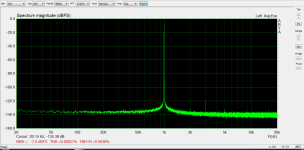
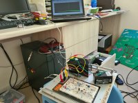
I've hooked up the circuit and done some tests. Note this is not as I posted earlier this is with 40.2K resistors, apparently my worry about needing to use lowest value resistors for good noise floor was unfounded. Appart from 40.2K instead of 1.3K resistors pretty much the same.
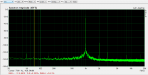
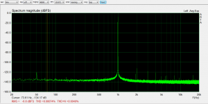
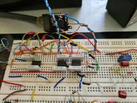
Attachments show the focusrite in balanced loopback, then in SE loopback, then with the circuit in between to convert SE to balanced for input. I'll edit and upload the photos to show the mess that is the breadboard. Proper layout with attention to earthing should result in distortion performance improvement, and placed in a metal box should remove the 50Hz pickup.
edit: also note that one of my 12V batteries is not happy and so the negative rail was around -8.4V instead of -12V so that certainly won't be helping things either the opamp further to the left is for the balanced to SE which I was not using. I just took tip and ring from the output to the input of the converter.
Tony.
Attachments show the focusrite in balanced loopback, then in SE loopback, then with the circuit in between to convert SE to balanced for input. I'll edit and upload the photos to show the mess that is the breadboard. Proper layout with attention to earthing should result in distortion performance improvement, and placed in a metal box should remove the 50Hz pickup.
edit: also note that one of my 12V batteries is not happy and so the negative rail was around -8.4V instead of -12V so that certainly won't be helping things either
the opamp further to the left is for the balanced to SE which I was not using. I just took tip and ring from the output to the input of the converter. Tony.
Attachments
Last edited:
Did you see the info at rod Elliott's page with regards to the topic?
Bridging Adapter For Power Amps
Bridging Adapter For Power Amps
Sorry guys/gals, just realize Rod´s site has been linked to already.
Strange there is no simple&cheap PCB out there for this.
All pretty expensive.
This is one is too much but would be nice for testing etc.:
BTSB Buffer - SE/Bal to SE/Bal Buffer GB
This one, unfortunately, is not a rectangle PCB. Otherwise it would be cheap to send the design for production (gerber files provided):
https://www.ti.com/tool/TIDA-01359
I might take Rod´s circuit (P87B) and make a simple PCB for it but will do some more searching (need a proper adapter for bridging amps)
- Status
- This old topic is closed. If you want to reopen this topic, contact a moderator using the "Report Post" button.