Placing CFB opamp in Class AA circuit
Hi,
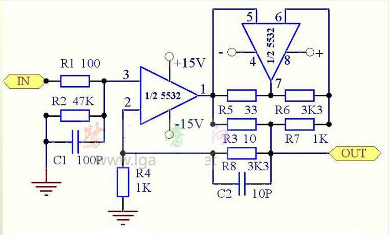
I have a PCB for this circuit. But I want to use a high current opamp instead of other half of of 5532 (the upside down one in schematic). As far as I know, the amplifier in feedback network provides the current.
I have LT1206's which is 250mA capable but they are current feedback op amps. I need to know that which components have to be altered when utilizing LT1206 instead 5532 in feedback network.
I plan to use two single soic-8 opamp to DIP-8 adapter instead of 5532. One half will be NE5534 other half will be LT1206.
Hi,
I have a PCB for this circuit. But I want to use a high current opamp instead of other half of of 5532 (the upside down one in schematic). As far as I know, the amplifier in feedback network provides the current.
I have LT1206's which is 250mA capable but they are current feedback op amps. I need to know that which components have to be altered when utilizing LT1206 instead 5532 in feedback network.
I plan to use two single soic-8 opamp to DIP-8 adapter instead of 5532. One half will be NE5534 other half will be LT1206.
Attachments
Last edited:
> As far as I know, the amplifier in feedback network provides the current.
No, both supply load current.
> LT1206's which is 250mA capable
Then this chip can supply many times the current of a '553x and can carry the load alone. I would just set up the LT1206 with 470r and 120r feedback resistors (>400r to satisfy the stability needs).
No, both supply load current.
> LT1206's which is 250mA capable
Then this chip can supply many times the current of a '553x and can carry the load alone. I would just set up the LT1206 with 470r and 120r feedback resistors (>400r to satisfy the stability needs).
> As far as I know, the amplifier in feedback network provides the current.
No, both supply load current.
> LT1206's which is 250mA capable
Then this chip can supply many times the current of a '553x and can carry the load alone. I would just set up the LT1206 with 470r and 120r feedback resistors (>400r to satisfy the stability needs).
I guess second opamp is there for a reason (from this thread):
new class A is an innovative bias circuit that keeps the output transistors in the ready state, eliminating crossover distortion, though keeping idling current low in order for more efficiency
So, Technics Class AA concept, hence the circuit relies on overcoming artifacts of the traditional Class-B switching which opamps rely on. Someone may say that just put a bias resistor across the output and negative rail but this concept seems doing the things different.
- Status
- This old topic is closed. If you want to reopen this topic, contact a moderator using the "Report Post" button.