Hi everyone, I'm trying to build a thing, but my cluelessness is just raising questions. I will use this thread as a log of my activity, and maybe if anyone can help that would be amazing.
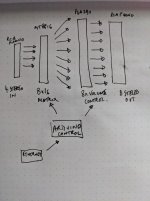
The general idea is a 4 stereo input 8 stereo output remote control (over Arduino with LAN) audio switch and volume control. I have 8 audio zones I wish to switch input to. I drew my general design attached to the thread. I am fine with the Arduino bit.
Constraint: prefer through-hole components. I am fine with getting and assembling SMT things, but these parts are expensive so I want to be able to screw up and not waste money.
Constraint: it just needs to sound "quite good" I am not an audiophile and these are mostly not for music.
The components I have sourced are the MT8816 matrix and the PGA2311 volume control. I'll need 1 matrix and 8 volume control chips. They both come in DIP so that is great.
Now down to the questions/discussions I already have.
1. Power supply. Both the matrix and volume chips require a dual supply +-5v and a digital 5v. I'm a bit confused about the difference between the analog power supply and digital power supply. Will I need two separate AC/DC converters? I have never worked with this before but I see some sources online on how to build these analog supplies. I'd prefer to buy the power supply from somewhere. Online I see something like https://www.renesas.com/eu/en/www/doc/datasheet/icl7660.pdf which can produce the -5v. Could I just use that for -5v and use +5v for the second rail and also the digital 5v?
2. Input / output buffers. The volume chips say they need "For optimal performance, drive the PGA2311 with a low source impedance." I don't really know what that means. Should I have some kind of buffer op-amp on the input before the matrix and also after the matrix before the volume chip?
3. Phono socket shared ground. All the twin phono socket pcb mounts I've found share a ground. e.g. https://www.mouser.co.uk/datasheet/2/670/rcj-22xx-1219155.pdf should I just join my left and right ground for each channel output from the volume chip?
I'll keep posting here, but thanks for any help or just pointers I can get in the meantime.
Attachments
Last edited:
1) You need a +5V digital supply that is separate from the two analog supplies.
Otherwise, you could have noise problems. Note that the digital supply ground
is only connected to the analog supply ground at a single point.
2) Before the PGA2311, the output pin of any op amp will be fine.
After the PGA2311, the positive input pin of any op amp connected
in the non-inverting mode will be fine.
3) Shared output grounds could cause hum in some circuits, so try to use
separate left and right output connectors, as per fig. 13 of the data sheet.
Last edited:
Hi Rayma, thanks for your help.
With 2)
a) Should I have an op amp before my matrix for each channel?
b) If a) is yes do I still need op amp after the matrix before the pga2311?
c) The PGA2311 outputs to my power amp, is that suffiecient or should I add extra op amp?
Thanks again.
With 2)
a) Should I have an op amp before my matrix for each channel?
b) If a) is yes do I still need op amp after the matrix before the pga2311?
c) The PGA2311 outputs to my power amp, is that suffiecient or should I add extra op amp?
Thanks again.
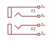
I have found some phono sockets with separate grounds - the horizontal ones which is annoying for space but I guess I have to.
The schematic is attached below... I really am not sure how to understand them though, does the signal go to 1/3 and the ground to 2/4 ?
The schematic is attached below... I really am not sure how to understand them though, does the signal go to 1/3 and the ground to 2/4 ?
Attachments
a) Should I have an op amp before my matrix for each channel?
b) If a) is yes do I still need op amp after the matrix before the pga2311?
c) The PGA2311 outputs to my power amp, is that suffiecient or should I add extra op amp?
a) Yes.
b) Yes
c) Need op amps (in noninverting mode) at PGA2311 outputs
Last edited:
I have found some phono sockets with separate grounds - the horizontal ones
which is annoying for space but I guess I have to.
Other example parts, some vertical:
Phono Jacks
Phono Jacks, Color-Keyed: Keystone Electronics
RCA Connectors - Parts Express
Last edited:
a) Yes.
b) Yes
c) Need op amps (in noninverting mode) at PGA2311 outputs
Thank you Rayma you have again been amazingly helpful and generous. Could I please just follow up here.
1) For a) and b) should I use the op amp in "voltage follower" (second attachment) mode. And c) in "non-inverting amplifier" (first attachment) mode?
2) For the non-inverting amplifier on the PGA2311 output what kind of gain should I look to achieve. I was thinking of 1 or 2
3) Is LM833 a suitable op amp for this application?
I attached some schematics to show what I mean because I am new to op amps and trying to learn fast.
Thanks very much
Attachments


- Status
- This old topic is closed. If you want to reopen this topic, contact a moderator using the "Report Post" button.
- Home
- Source & Line
- Analog Line Level
- Remote control matrix switch - clueless newbie