Hi everyone.
I'm trying to design and build a simple relay volume control. I would like to do it with the requirements that I am going to list below:
- simplicity
- pure electronics, no PIC, microcontroller, firmware and software.
- easy to repair in case of failure
- single entrance
- remotely controlled with Ir or RF remote control
- no display in my opinion is not needed.
- no SMD but integrated with base so you can replace them without unsoldering.
- silent
- each relay of the signal group must have two separate contacts to obtain two channels
- functions: increase / decrease, mute / restore, storage of the volume prior to switching off.
I have already prepared the heart of the circuit but I ask you for some advice on choosing the components.
- which relays to use for the signal to obtain silence and long life?
- which single coil bistable relays to use to obtain silence and
lasting in time?
- which resistances to use?
- which configuration do you recommend to use for the resistance chain
? series? shunt? ladder?
- how to neutralize the micro-bounces of the relay contacts?
- which system to use to avoid overlapping two volumes
when do you change? I thought of inserting a small delay circuit when the relay is switched on. what would you do?
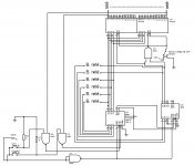
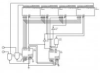
I briefly describe the circuit I have attached.
the two counters in cascade CD40193 have 2 inputs to increase or decrease, they control two 74HC154 and the outputs of the latter go to control the relays dedicated to the signal.
by enabling or disabling the two inputs E2 of the 74HC154 the mute / reset function is obtained.
the NAND U1 gate has the function of updating the outputs with the inputs of the CD40193 at power on, through the LOAD input.
the six bistable relays have the function of memorizing the volume prior to switching off.
of course the circuit is not complete, the remote control circuit is missing, the one that controls the bistable relays, the delay circuit of the signal relays.
Invia commenti
Cronologia
Salvate
Community
I'm trying to design and build a simple relay volume control. I would like to do it with the requirements that I am going to list below:
- simplicity
- pure electronics, no PIC, microcontroller, firmware and software.
- easy to repair in case of failure
- single entrance
- remotely controlled with Ir or RF remote control
- no display in my opinion is not needed.
- no SMD but integrated with base so you can replace them without unsoldering.
- silent
- each relay of the signal group must have two separate contacts to obtain two channels
- functions: increase / decrease, mute / restore, storage of the volume prior to switching off.
I have already prepared the heart of the circuit but I ask you for some advice on choosing the components.
- which relays to use for the signal to obtain silence and long life?
- which single coil bistable relays to use to obtain silence and
lasting in time?
- which resistances to use?
- which configuration do you recommend to use for the resistance chain
? series? shunt? ladder?
- how to neutralize the micro-bounces of the relay contacts?
- which system to use to avoid overlapping two volumes
when do you change? I thought of inserting a small delay circuit when the relay is switched on. what would you do?
I briefly describe the circuit I have attached.
the two counters in cascade CD40193 have 2 inputs to increase or decrease, they control two 74HC154 and the outputs of the latter go to control the relays dedicated to the signal.
by enabling or disabling the two inputs E2 of the 74HC154 the mute / reset function is obtained.
the NAND U1 gate has the function of updating the outputs with the inputs of the CD40193 at power on, through the LOAD input.
the six bistable relays have the function of memorizing the volume prior to switching off.
of course the circuit is not complete, the remote control circuit is missing, the one that controls the bistable relays, the delay circuit of the signal relays.
Invia commenti
Cronologia
Salvate
Community
Attachments
Hello .
if I'm wrong, correct me as well.
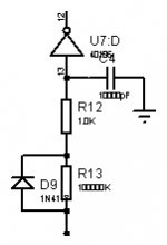
for the delay circuit I thought of the attached one.
must be applied to the outputs of the 74HC154.
the door is a schmitt trigger and the values are randomly placed just to show the pattern. in reality the values of resistors and capacitors must be calculated based on the opening / closing times of the relays
if I'm wrong, correct me as well.
for the delay circuit I thought of the attached one.
must be applied to the outputs of the 74HC154.
the door is a schmitt trigger and the values are randomly placed just to show the pattern. in reality the values of resistors and capacitors must be calculated based on the opening / closing times of the relays
Attachments
with regard to the six bistable relays which must report the outputs of the 40193 to their respective inputs.
the micro bounces on the relay contacts could cause strange behavior of the counters.
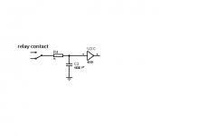
to avoid this I know two systems.
the first is an RC with a non-inverting schmitt trigger. One of the two ends of the relay contact goes one to ground and the other to V + (also here the values of RC are to be calculated).
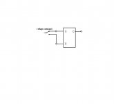
the second circuit instead is a single output SR latch, in this case the only end of the relay contact will go to ground or to V + depending on the type of flip flop the latch is made of.
there is 74118 which has six latches but I don't know if it is still in production.
the micro bounces on the relay contacts could cause strange behavior of the counters.
to avoid this I know two systems.
the first is an RC with a non-inverting schmitt trigger. One of the two ends of the relay contact goes one to ground and the other to V + (also here the values of RC are to be calculated).
the second circuit instead is a single output SR latch, in this case the only end of the relay contact will go to ground or to V + depending on the type of flip flop the latch is made of.
there is 74118 which has six latches but I don't know if it is still in production.
Attachments
there are two types of bistable relays.
single coil or with two coils.
in the first when the current flows in one direction it closes the contact, vice versa when it flows in the opposite direction it opens the contact.
in the second one of the two coils is dedicated to contact closure and the other coil to contact opening.
single coil or with two coils.
in the first when the current flows in one direction it closes the contact, vice versa when it flows in the opposite direction it opens the contact.
in the second one of the two coils is dedicated to contact closure and the other coil to contact opening.
Beware of the pop/click free brag in that thread.
It is obscured by:
A gimmick, in a sequencing of the relay changes, that hide some, but doesn't solve the real issue.
"Rearranging the deck chairs on the Titanic".
And a diversion to zero crossing swiching, something that one cannot think of seriously with relays, anyway.
Relays are way too slow for a pop/click free operation.
is it correct to say that pop / click problems are the prerogative of this configuration?
with the next questions I am not referring to this project but in general to this type of configuration. I would like to know in how many ways the bit row of a multiple contact attenuator can be originated and how the link between track and relay is implemented. for example what is the bit sequence for each step?
is there a web page where it is explained well?
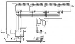
perhaps someone has noticed that there is no longer the possibility of implementing the mute function because all the enable pins of the 74HC154 are occupied.
in retrospect I think this function placed on the volume control is useless because the player continues to play the music. so pausing the player is better.
if instead it were necessary for some reason that I now ignore, you can add four AND gates and get the mute function back.
or you can use the two "clear" inputs of the CD40193
Last edited:
Hello.
During this time I did a 360 ° search.
Mainly 4 configurations can be used to make an attenuator:
series, shunt, parallel, ladder.
Tip_67
Logarithmic resistor ladder - Wikipedia
I don't like the shunt configuration, that series (in my case you would use the circuit of post n ° 13) and parallel make use of many relays unless you do that series with 32 steps or even less instead of 64, so I chose the logarithmic version six relay ladder resistor.
there are three types of bistable relays:
FIG. bistable latch relays
type A one coil and two terminals (current flows in both directions) type B 2 coils and three terminals (current flows in one coil or the other in the same direction) type C 2 coils and four terminals (to be discarded).
Once I had chosen the ladder configuration I had to decide which relays I should use.
The choice fell on type A and B.
I looked for what could be the techniques to drive a single coil bistable relay, among the solutions I found the only one I like more than the others is the H-bridge but they have four inputs and need a relatively complex additional circuit, So I came up with a way to do the piloting. Basically it is a question of using a dual power supply made in such a way as to allow the relay coil to discharge the surge surge.
FIG. power supply circuit
when the power disappears, the coil discharges through the zener and the diodes.
To drive the coil I thought of the push-pull transistor.
Another problem was the non-volatile memory. There are integrated circuits in parallel configuration such as F-rams but they require a complex driver circuit.
so here too I have invented an alternative, to exploit the driving current of the single coil bistable relays to control a one-bit memory.
It involves using small cut toroids wound by a coil and combined with a magnetic sensor.
FIG. toroid + sensor
there are toroids composed of a material called soft magnetic, it is located halfway between a permanent magnet and a normal ferromagnetic material, can reach 2 tesla. when current is made to flow in the coil that surrounds this material a magnetic field is formed, when current is made to flow in the opposite direction the magnetic field changes polarity. The magnetic field remains even in the absence of current, this is due to the fact that this material has a large magnetic remanence.
Remanence - Wikipedia
you have already understood, therefore, that an impulse is enough for piloting.
But that's not all, there are many soft magnetic materials and each one has a hysteresis with a different shape, the one most suitable for this purpose has a very narrow and vertical hysteresis in the shape of an inverted Z.
FIG. hysteresis
in the image below you can see how the hysteresis width can be different depending on the material used.
FIG. Hysteresis width
unfortunately I have not yet identified the right material, maybe you can help me. the amorphous ones or the nanocrystalline ones bode well.
the second step is the choice of the magnetic sensor.
There are Hall-effect switch latch sensors that act like an SPDT switch and that's just what you need. These also have a small hysteresis but its function is to eliminate the uncertainty of the output when the magnetic field slowly transitions from one magnetic polarity to the opposite one. The operation of this memory is simple, when the whole circuit is powered, the output of the Hall-effect magnetic sensor is in a high or low state depending on the magnetic polarity of the toroid. in my opinion it is an elegant way to create a 1 bit memory using the same impulse that drives the relays.
Let's now turn to the circuits. I found 4 different ways to make the attenuator. The IC infrared decoder, 2x4093 on the left, 4068, 4078 are common to all the circuits, they are used to control the inputs of the two counters and to stop when the volume is minimum or maximum. except the last one, the other circuits have dual power supply.
1) The first circuit I describe is the one that makes use of the singular memory I described above (toroid + Hall sensor).
The second group of 4093 you see on the right has 2 functions: at power up with a pulse it updates the outputs of the 40193s according to the state of the memory and activates the high impedance state of the six tri-state buffers so that the push pull cannot get a wrong impulse. After the delay group 40106 there are the OPamps which have the task of creating the positive or negative impulse.
The relays are of type A
FIG. toroid memory volume + Hall
2) the second circuit is the same as the previous one except for some things. the components double, then the relays become twelve. The memory is realized through a contact of the relays.
If desired, it is possible to modify this circuit to create an independent volume for each channel, just create a separate command for each input of the pairs 40193.
the relays are of type A
FIG. relay memory volume
3) The third circuit makes use of a buffer battery that keeps the two 40193s powered even when there is no mains voltage so there is no need for a memory (I don't know how long a buffer battery can last before discharging). Consequently, to protect the inputs of the 40106s that come later I have interposed solid state relays. Each time the electricity returns, the 6 delay groups 40106 transmit to the OPamps the status of the outputs of the two 40193s which in turn send a pulse to the push pull transistors. Here there are no tristate buffers before the push pulls because even if an impulse arrives at the relays when the voltage returns, they do not change their state.
The relays are type A
FIG. buffer battery volume
4) The last circuit has the advantage of not making use of the dual power supply.
Instead of the OPamps there is a small circuit made up of three 40106s, the outputs alternately supply a pulse of the same sign.
FIG. 40106 + PNP transistor
I have not decided which memory is better for this circuit so I deliberately omitted to insert it, you can use a buffer battery or a relay contact but in this case the components become many, you cannot use the one with toroid and Hall sensor, also missing the tri-state buffer and solid-state relay.
Unlike all other circuits, in this case the relays are type B
FIG. volume 40106
which of these do you like best? and why ?
I'm working on an LDR version, let's see what comes out.
for ICs you can use the sockets for integrated as used in the old school in order to change them without unsoldering in case of failure.
then a row of LEDs can be added next to each component stage to verify their operation.
you don't usually think about it but being able to repair your electronic circuit without sending it somewhere to get it repaired is an advantage.
any comments on the circuit diagrams?
then a row of LEDs can be added next to each component stage to verify their operation.
you don't usually think about it but being able to repair your electronic circuit without sending it somewhere to get it repaired is an advantage.
any comments on the circuit diagrams?
- Home
- Source & Line
- Analog Line Level
- volume control relè