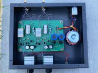
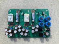
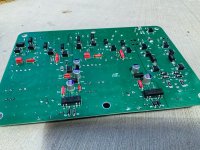
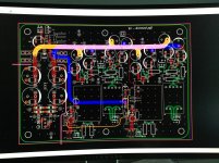
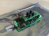
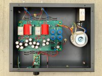
My latest diy preamp adventure. -/+ 24v Linear Supply. Sparkoslabs regulators. LSK489 for the jfet’s. 6 layer PCB (s/g/p/p/g/s). Startup / shutdown muting.
Balanced -> LL1676(1:2) -> jfet follower -> 10k ladder -> jfet follower -> dc blocking cap -> RCA
I will post measurements soon.. the in/out are flipped on the case.
Balanced -> LL1676(1:2) -> jfet follower -> 10k ladder -> jfet follower -> dc blocking cap -> RCA
I will post measurements soon.. the in/out are flipped on the case.
Attachments
Round #2
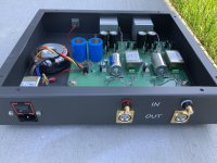
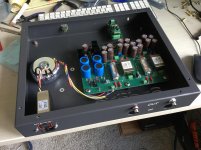
Transformer configured 1:1. Isolated the PS better plus additional filtering. Removed Jfet v-reg’s and replaced with low pass filters. Waiting on new case. Also integrating Tortuga Audio’s new ldr volume attenuator.
Electronic Stepped Attenuator | ePot.V3 Mini | Tortuga Audio
Dwight
Transformer configured 1:1. Isolated the PS better plus additional filtering. Removed Jfet v-reg’s and replaced with low pass filters. Waiting on new case. Also integrating Tortuga Audio’s new ldr volume attenuator.
Electronic Stepped Attenuator | ePot.V3 Mini | Tortuga Audio
Dwight
Attachments
Last edited:
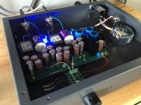
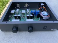
Ever heard of an oxymoron?Still have a little hum with my 97db speakers.. but otherwise it’s a killer preamp.
Your power amp isn't also IEC Class I by any chance? (If not, does its power xfmr have a shield winding?) With all the work you've put in, it would suck to have a ground loop in the setup.
Also, XLR pin 1 hookup is not AES48 compliant by the looks of it, should go straight to chassis instead. And twisted pair arguably isn't first choice for hooking up RCAs, consider something closer to coaxial wiring.
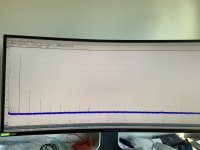
Not sure I would trust a Picoscope for audio work, I mean, it's a scope and not an audio analyzer. Would suggest rechecking distortion via a decent USB soundcard / audio interface input on a battery-powered laptop. The levels displayed earlier would not be very much to write home about.
Thank you for the response. Attached a better pic of the build..
Here is a link to my amp. The Amp’s ground lift switch does remove the hum.
Vision SET 120 Power Amplifier – Audio by Van Alstine
I have located a chassis ground point near the xlr inputs. To be honest , I couldn’t decide which direction to go. It won’t take much to wire it")
I have ordered a Mu shielded toroid.
https://www.mouser.com/ProductDetai...w%2bjEpvjHw==&countrycode=US¤cycode=USD
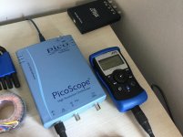
I have attached a link for the pic scope I am using.
16 bit high resolution oscilloscope | Overview
Balanced Signal Generator.
MR-PRO Audio Generator
I will attach the lastest FFT on my next post.
And once again.. thank you for your insight !
Dwight
Here is a link to my amp. The Amp’s ground lift switch does remove the hum.
Vision SET 120 Power Amplifier – Audio by Van Alstine
I have located a chassis ground point near the xlr inputs. To be honest , I couldn’t decide which direction to go. It won’t take much to wire it
I have ordered a Mu shielded toroid.
https://www.mouser.com/ProductDetai...w%2bjEpvjHw==&countrycode=US¤cycode=USD
I have attached a link for the pic scope I am using.
16 bit high resolution oscilloscope | Overview
Balanced Signal Generator.
MR-PRO Audio Generator
I will attach the lastest FFT on my next post.
And once again.. thank you for your insight !
Dwight
Attachments
Last edited:
Looks like legit backyard highend. Unbalanced inputs only, IEC Class I, ground lift switch. Why then do you have a preamp with balanced outputs?Here is a link to my amp. The Amp’s ground lift switch does remove the hum.
Vision SET 120 Power Amplifier – Audio by Van Alstine
Wait, those are female XLR jacks - i.e. inputs. They're just labeled wrong then, I guess. Oh, you even mentioned that in your first post. Threw me for a bit of a loop there.
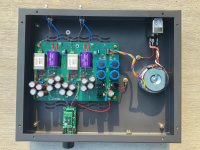
You placed the transformers on the input and the output is ground-referenced, right? And ground goes to chassis which is earthed.
I'm sorry to say, you'll have to keep using the ground lift switch in this combination. You have an unbalanced connection between two IEC Class I devices otherwise (those being your preamp and the power amp), which is fundamentally broken as you can hear.
Your project would have made more sense to me if you had had transformer-coupled, floating RCA inputs, XLR outputs, and a power amp with XLR inputs. One of those could have been used to drive something using Hypex nCore or Purifi Class D modules or a solid vintage PA amp like an '80s Yamaha or something.
Last edited:
Member
Joined 2009
Paid Member
Bigun,
The case is from Protocase Designer | The fastest and easiest way to design, price and build custom electronics enclosures its Aluminum but steel is also available. I like the Clarity CSA'S. Not super expensive.
Marconi118,
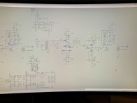
Here is the SCH for one side ! Sorry for the delay Pretty simple design. LSK489's sound lovely. They need to be sorted. Lots of low Idds.. Buy a bunch !
Dwight
The case is from Protocase Designer | The fastest and easiest way to design, price and build custom electronics enclosures its Aluminum but steel is also available. I like the Clarity CSA'S. Not super expensive.
Marconi118,
Here is the SCH for one side ! Sorry for the delay
Pretty simple design. LSK489's sound lovely. They need to be sorted. Lots of low Idds.. Buy a bunch ! Dwight
Attachments
Last edited:
- Status
- This old topic is closed. If you want to reopen this topic, contact a moderator using the "Report Post" button.
- Home
- Source & Line
- Analog Line Level
- Transformer based 6db preamp