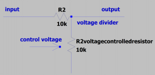
I am building an audio compressor and I am using a voltage divider. If I lower the voltage of the voltage controlled resistor as shown in the schematic, the voltage is cut in half and this is a 6db loss of voltage. How do you figure out what the compression ratio is? is this 2:1, 6:1 etc as shown?
Attachments
Does your "voltage controlled resistor" really cut Voltage linearly? Or Resistance?
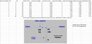
Set up a spreadsheet.
Vin -- Rvar ---- Rvar/(R2+Rvar) --- Vout
0V --- 20k ---------- 0.66 ----------- 0V
1V --- 10k ---------- 0.50 ----------- 0.5V
2V ---- 5k ---------- 0.33 ----------- 0.66V
3V -- 3.3k ---------- 0.25 ----------- 0.75V
3:1 input rise makes 1.5:1 output rise. We normally work in dB, so 9.5dB input makes 3.5dB output rise, 2.7:1 CR, *over this small range of inputs*.
I do not know of any physical single-part "voltage controlled resistor" with a simple predictable control law.
Also an audio compressor normally has a "threshold" below which it does not act.
And the gain law is a product of several factors including sidechain gain.
Here is a worksheet for a functional real-parts limiter (tube and opamp). The tube gain law is very curved, and varies tube-to-tube. But the limiter works feedback which makes it much less sensitive to the tube used. But not a lot of feedback so it does not squash the dynamics flat.
I see I did not compute the compression ratio. Take the range from 100mV to 1V, a 20dB rise of input. The output rises from 215mV to 550mV, 8dB. So CR is 20:8 or 2.4.
Code:
__ in _ dBin __ out _ dBout __ Gv ___ GR __ dBgr ___ CV ___ THD __ mA
__ 10 _ -30 ____ 27 _ -23 ____ 2.7 __ 1.0 ___ 0 ____ 0.3 __ 0.02 _ 19
_ 100 _ -10 ___ 215 __ -5 ____ 2.2 __ 0.8 ___ 2 ____ 2.2 __ 0.08 _ 10
_ 300 ___ 0 ___ 392 ___ 0 ____ 1.3 __ 0.5 ___ 6 ____ 4.0 __ 0.08 __ 4
__ 1V __ 10 ___ 550 ___ 3 ____ 0.5 __ 0.2 __ 14 ____ 5.5 __ 0.4 ___ 1.3
__ 2V __ 16 ___ 620 ___ 4 ____ 0.3 __ 0.11 _ 19 ____ 6.4 __ 2 ____ 0.6
__ 3V __ 20 ___ 650 ___ 4.4 __ 0.2 __ 0.08 _ 22 ____ 7 ____ 5 ____ 0.55
__ 6V __ 26 ___ 672 ___ 4.7 __ 0.11 _ 0.04 _ 27 ____ 8 ___ 20 ____ 0.4
_ 10V __ 30 ___ 690 ___ 4.9 __ 0.07 _ 0.025_ 32 ___ 10 ___ 37 ___ 0.014
Last edited:
Thank you for the very helpful answer. I think I see how this works now. I did create a spreadsheet and that helped.
Basically I have made several different compressors and I've built them with a similar format. The R2 is variable resistor to control the ratio, then I have another resistor forming a voltage divider, and there is another "voltage controlled resistance type device" which I am showing in the attached figure. The idea is to use a device who's resistance is large compared to the resistor when the control voltage is low and small compared to the resistor when the control voltage is high.
I wanted to label the ratio potentiometer in some way, so it looks like I'll be labelling it as a maximum compression when a signal starts well below threshold to well above.
The last compressor I built uses 4 diodes and the one before that used an led/photoresistor combination. (I also made one using some transistors, but its more of an all or nothing reduction which believe it or not when used properly didn't sound too bad). The 10k resistors shown in the schematic are arbitrary for the sake of discussion. For the diode compressor I'm actually using 100k voltage divider as shown, I think I used 20k for the optocompressor.
This really helped me, thanks again.
Attachments
Last edited:
Hello. I am extremelly interested in this post so I will make an attempt to revive it hoping for the best.
@garybdmd: I would love to know, what is the point of the voltage controlled resistor since you determine the ratio with the R2 (assuming it's a potentiometer)?
I am building a FET feedback compressor and am now in the process of trying to determine the compression ratio for the given control voltage.
Sorry but no.3:1 input rise makes 1.5:1 output rise.
We are talking ratios here, not absolute values.
So if input rises 3:1 , output also rises 3:1 , in both cases no units involved, only ratio which is dimensionless number.
Where are you pulling these numbers from?We normally work in dB, so 9.5dB input makes 3.5dB output rise, 2.7:1 CR, *over this small range of inputs*.
Again we are talking a ratio here, only measured in dB, so if input rises by 9.5dB, output rises also by 9.5dB , whatever the absolute value is.
Think LDR, FET, etc.I do not know of any physical single-part "voltage controlled resistor" with a simple predictable control law.
Even Tubes and Bipolars can be used as such, only they re not too linear, but quite useable within a limited range.
True, but not relevant to what´s being asked.Also an audio compressor normally has a "threshold" below which it does not act.
And the gain law is a product of several factors including sidechain gain.
Signal feedback is nonsense in a compressor/limiter/expander because it makes output signal fixed level, negating the processor purpose which is to vary gain one way or the other.Here is a worksheet for a functional real-parts limiter (tube and opamp). The tube gain law is very curved, and varies tube-to-tube. But the limiter works feedback which makes it much less sensitive to the tube used. But not a lot of feedback so it does not squash the dynamics flat.
'Signal feedback is nonsense in a compressor/limiter/expander because it makes output signal fixed level, negating the processor purpose which is to vary gain one way or the other'
Not sure what you mean. This is not true if the circuit is configured correctly. I.e. the variable element is the feedback resistor in a non-inverting amp. The output of the non-inverting amp feeds the rectification which controls the variable element. A pot controls rectification gain. Everything is in a feedback loop.
Not sure what you mean. This is not true if the circuit is configured correctly. I.e. the variable element is the feedback resistor in a non-inverting amp. The output of the non-inverting amp feeds the rectification which controls the variable element. A pot controls rectification gain. Everything is in a feedback loop.
Last edited:
That is the correct way but *as written* it means a variable gain stage was built, and then plain NFB was applied output to input which of course washes out variable gain action, by definition.
If meaning voltage controlled NFB is used to vary gain (there are other methods available) then it should specifically have been mentioned.
Again: as is syntaxis is confusing.
If meaning voltage controlled NFB is used to vary gain (there are other methods available) then it should specifically have been mentioned.
Again: as is syntaxis is confusing.
- Home
- Source & Line
- Analog Line Level
- How do I figure out the Compression Ratio from Voltage Divider