Why do you map the expected maximum level from the cartridge to -20 dB? To keep headroom for scratches or inaccuracies in your estimate?
What noise level do you get when you divide the ADC's input noise by the preamp gain?
I can't read the pictures, for some reason I only get a very poor resolution version on my screen.
Well, both for head room for pops and scratches and to keep the adc in it's most linear operating region. Nice coincidance in this case these overlap.
Couple of measurements of the adc board are on the ASR forum:
Cheap High Quality ADC | Audio Science Review (ASR) Forum
Last edited:
Hi all,
The build is proceeding slowly but i'm almost done. Just need to mount the AD8221 amps and load the DSP with the filters.
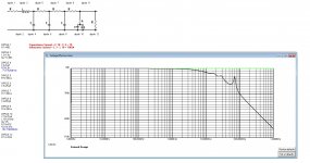
I have also been busy trying to model the complete cart - cables - pre-amp system. See attached model and Frequency response.
Looks like I`m on the right track, any pointers tough?
I've modeled the cart as a pure resistance (495 Ohm) and a damped inductance (1H/495 Ohm, Q=12.694@1KHz). after that the TT wiring (0.1 Ohm / 25pF), the interconnect (0.1 Ohm / 55pF) and the inamp (0.1 Ohm / 75pF), terminating in the very high input impedance of the inamp (modeled as 10M Ohm).
If at all accurate I like to use this model as a stareting point for cart EQ.
The build is proceeding slowly but i'm almost done. Just need to mount the AD8221 amps and load the DSP with the filters.
I have also been busy trying to model the complete cart - cables - pre-amp system. See attached model and Frequency response.
Looks like I`m on the right track, any pointers tough?
I've modeled the cart as a pure resistance (495 Ohm) and a damped inductance (1H/495 Ohm, Q=12.694@1KHz). after that the TT wiring (0.1 Ohm / 25pF), the interconnect (0.1 Ohm / 55pF) and the inamp (0.1 Ohm / 75pF), terminating in the very high input impedance of the inamp (modeled as 10M Ohm).
If at all accurate I like to use this model as a stareting point for cart EQ.
Attachments
Yupz, came across that site. The model seems a bit simple unfortunately.
The cart will behave primarily as a inductance with a low Q (because of the sizable resistance, 990 Ohms with my cart). But of course there will also be interwiding capacitance.
Now the L and R are specified for the cart I have (1H and 990 Ohms @1KHz), but not the capacitance. This is of course an important part when trying to simulate it.
Did run some simulations during lunch, anything over ~10pF would seem to introduce major frequency response flukes. So for now that's the value I`m using, but not sure at all if that's anywhere near accurate.
The key message from Werner's article is that ignoring the mechanical resonances and equalization and focusing primarily on the electrical parameters will not lead to optimal results.
In addition to the electrical equalization interaction between generator coil inductance - resistance - parasitic capacitance, tonearm cabling, and phono stage input load, phono cartridges further implement mechanical equalization in the form of a suspension and/or rubber damping.
Regarding moving coil cartridges, the electrical resonances occur at such high frequencies that the audible frequency response is mostly due to the interaction between cantilever-stylus resonance characteristics and the mechanical equalization of the suspension and dampers. I.e., the interaction between electrical resonances and phono stage input load are usually ignored.
In the case of most fixed-coil cartridges, the mechanical interactions between cantilever-stylus resonance characteristics and suspension-damper equalization remain, but additionally the electrical resonances occur at audible or near-audible frequencies, and must also be taken into account.
Cartridge manufacturers have access to a number of damper formulations (as well as shapes and sizes), which they select from to counter the effects of the cantilever-stylus resonances and electrical resonances. The mechanical equalization used depends on the individual cartridge design; there isn't any need for standardization, since it is sufficient if the sum result of the mechanical and electrical interactions measures acceptably.
However, if you are determined to pursue the electrical-only path, the "capacifier" approach seems the most promising. There used to be a thread on the Vinyl Engine, but I can no longer find it. Perhaps some clues can be found in the following 168-page long thread on diyAudio.
mechanical resonance in MMs
Thanks! Got some reading to do...
The reason I`m interested in a fairly accurate model is because I`m trying to model an IIR filter in DSP, EQ-ing the HF response to somehwere near flat.
If I manage to get the model somewhat accurate it should be easy to change this EQ if I ever mount a different cart. Also fun to do
The mechanical system is a given, electrical also mostly (can play around with the loading a bit, but not that much).
The key message from Werner's article is that ignoring the mechanical resonances and equalization and focusing primarily on the electrical parameters will not lead to optimal results.
But if you don't know what the mechanical resonances are then you don't know how to adjust the electrical parameters to get the net result you want. Flattening the electrical response to be able to measure the mechanical response would therefore seem to be something worth trying, if only to get some data in the public domain. I see so many people on line fighting two variables without understanding either. Plus would be very interesting to find which cantilever model is closer to correct.
However, if you are determined to pursue the electrical-only path, the "capacifier" approach seems the most promising. There used to be a thread on the Vinyl Engine, but I can no longer find it. Perhaps some clues can be found in the following 168-page long thread on diyAudio.
mechanical resonance in MMs
Luckythedog's threads in VE got purged for some reason but the thread you linked meanders around various methods. Some of which I have on the bench waiting time to measure. There are several valid methods. The cordell damped RIAA is possibly the easiest to implement as you minimise noise penalty and add a zero in the RIAA response . Transimpedance loading only works with a few cartridges sadly. Right now it seems that minimal C and variable R might be the best bet for MM. That or lo-Z carts like the technics EPC-205CIIL if you can find a working stylus for it.
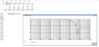
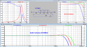
Attached is the electrical simulation of the AT150MLx that Hans did. This is a cartridge I am looking forward to experimenting with as the electrical model works well with an achievable capacitive load and works with a current mode phono stage. Hopefully I can tease out the mechanical response using this.
Attachments
It's working!
Build is almost done, need to do some metal work on the case but the electronics are all up and running.
Performance is not yet what it should be unfortunately. I've got a hum problem. Not really sure how it's picking it up. With the inputs terminated with a 50 Ohm resistor it's really silent, no hum, buzz or noise. Inputs open and there is a bad hum / buzz. TT connected the hum is less but still there.
Also need to order a soundcard with S/P-dif input so I can take some measurements..
Build is almost done, need to do some metal work on the case but the electronics are all up and running.
Performance is not yet what it should be unfortunately. I've got a hum problem
. Not really sure how it's picking it up. With the inputs terminated with a 50 Ohm resistor it's really silent, no hum, buzz or noise. Inputs open and there is a bad hum / buzz. TT connected the hum is less but still there.Also need to order a soundcard with S/P-dif input so I can take some measurements..
Attachments
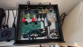
Finished the HW part of the build today, casework is all done.
Also did a bit of fine-tuning of the DSP. All the details are in the attached zip (Excel sheet inside).
Impatiently waiting for my inverse RIAA filter now, should arrive this week. I'll use my mAudio mobile pre for now and my Topping DX7pro DAC.
Already sounds nice
Also did a bit of fine-tuning of the DSP. All the details are in the attached zip (Excel sheet inside).
Impatiently waiting for my inverse RIAA filter now, should arrive this week. I'll use my mAudio mobile pre for now and my Topping DX7pro DAC.
Already sounds nice
Attachments
Hi all,
Finally got my measurement setup up and running. I got an inverse RIAA filter with spec (and measurement report; RIAA Inverse Filter for testing RIAA Pre-Amp | eBay) and a Focusrite Scarlett 8i6. So Analog out and S/PDIF in.
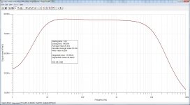
Did the first measurements yesterday, and of course I needed to do some tweaking. I did find some issues. Gain was a bit to high, but after tweaking the gain in the DSP the frequency response is dead on, really flat.
THD is also good in general, about 0.03%. Noise is still a bit disapointing (~1%) but this also seems related to my measurement setup.
After a stepped sine measurement using REW with 16x averaging, 96 steps and max FFT lenght (takes a really long time BTW) it is clear I still have a 50Hz problem. The interference is about 25dB above the noise floor. Also some 50Hz harmonics are visible.
Any tips on how to tackle that? A secondary linear regulator maybe, dropping the supply to +/-12VDC for the AD boards.
Also I noticed that when I use a 1:1 transformer coupling the Focusrite to the inverse RIAA filter my noise floor drops considerably. Could it be that using transformers like these: 0dB 10kohm signaltransformer 1:1 is a good way to make the analog input more robust?
Finally got my measurement setup up and running. I got an inverse RIAA filter with spec (and measurement report; RIAA Inverse Filter for testing RIAA Pre-Amp | eBay) and a Focusrite Scarlett 8i6. So Analog out and S/PDIF in.
Did the first measurements yesterday, and of course I needed to do some tweaking. I did find some issues. Gain was a bit to high, but after tweaking the gain in the DSP the frequency response is dead on, really flat.
THD is also good in general, about 0.03%. Noise is still a bit disapointing (~1%) but this also seems related to my measurement setup.
After a stepped sine measurement using REW with 16x averaging, 96 steps and max FFT lenght (takes a really long time BTW) it is clear I still have a 50Hz problem. The interference is about 25dB above the noise floor. Also some 50Hz harmonics are visible.
Any tips on how to tackle that? A secondary linear regulator maybe, dropping the supply to +/-12VDC for the AD boards.
Also I noticed that when I use a 1:1 transformer coupling the Focusrite to the inverse RIAA filter my noise floor drops considerably. Could it be that using transformers like these: 0dB 10kohm signaltransformer 1:1 is a good way to make the analog input more robust?
Last edited:
Hi all,
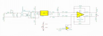
I see a lot of weird things happening, probably due to RF interference. So I decided to rework the complete input stage (with proper filters) and simulate it.
See attachments.
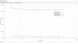
Any comments? S/N looks good I think, THD also.
I see a lot of weird things happening, probably due to RF interference. So I decided to rework the complete input stage (with proper filters) and simulate it.
See attachments.
Any comments? S/N looks good I think, THD also.
Attachments
Hi Hans,
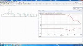
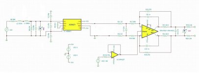
The design evolved a bit since I posted this. But basically the CM bead is to keep Cm RF out of the inamp. The capacitors serve the same function (all from the datasheet of the inamp). Values are to large in my previous post but it is a CM and DM RF filter.
C5 and R13 are a zobel for the transformer.
The transformer is in there because I noticed a drop in noise floor when I tried it, shouldn't be necessary for CMRR because the inamp is plenty good enough for that.
The model of the cart (AT-XP5) is in there to see what the Fresponse will be with all the filtering I put before the inamp.
The OPA1632 is part of the PCM4222EVM i'm using as A/D converter.
Attachments
What about this to start with:
1) your cart is 990R+1H. The 15K that you added makes little sense, the impedance @1Khz is specified at 6k7.
2) the CMRR for the AD8421 is excellent, the caps C1-C3 are more than adequate to deal with the CM noise injected over the interlink, making the CM coil obsolete.
The Caps C1-C3 and the capacity of the interlink cope additionally with DM noise making the transformer obsolete.
3) most MM Carts have 1 pin connected to Gnd. I expect the same for your Cart.
4) R7 100R has no function because of 3)
5) U2 the OPA1611, serves to make the output differential, why is that.
No additional info is added and with the resistors R11,12,17and 18 the input to the OPA1632 stays balanced. This level shifting is overcomplete.
Hans
Attachments
Hi Hans,
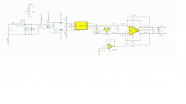
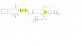
Thank you for your input, I did some more work on it today and reached the same conclusion for the most part (the 100r resistor was actually 100G, just for the sim).
The AD8421 (AD8429 in the latest iteration) needs a DC path to GND, hence the 10M resistor. I dropped the input Xformer and CM choke, just the beads are left in for now (as per the datasheet recommendation).
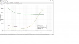
Noise performance now looks good I think, harmonic distortion not yet so much (1KHz 16 harmonics @ 100ms 38%)
Edit, made a sim mistake, signal source was still on square wave, THD is 0.158% with a 1Khz 7.78mvP sine wave as input. So some room for improvement left.
Thank you for your input, I did some more work on it today and reached the same conclusion for the most part (the 100r resistor was actually 100G, just for the sim).
The AD8421 (AD8429 in the latest iteration) needs a DC path to GND, hence the 10M resistor. I dropped the input Xformer and CM choke, just the beads are left in for now (as per the datasheet recommendation).
Noise performance now looks good I think, harmonic distortion not yet so much (1KHz 16 harmonics @ 100ms 38%)
Edit, made a sim mistake, signal source was still on square wave, THD is 0.158% with a 1Khz 7.78mvP sine wave as input. So some room for improvement left.
Attachments
Last edited:
10Meg is just producing lots of noise, Make it 1R and see what happens.
Distortion at 0.15% is taken at what point ?
Behind the AD4821 it seems insane with a gain of only 15.
I would expect 100 times less.
I will do the sim and let you know the outcome.
Hans
Oh I see you changed the gain from 15 to ca. 66 right ?
Distortion at 0.15% is taken at what point ?
Behind the AD4821 it seems insane with a gain of only 15.
I would expect 100 times less.
I will do the sim and let you know the outcome.
Hans
Oh I see you changed the gain from 15 to ca. 66 right ?
- Status
- This old topic is closed. If you want to reopen this topic, contact a moderator using the "Report Post" button.
- Home
- Source & Line
- Analog Line Level
- Overload margin in Phono pre-amp