After all this effort, don't you think a classic all in one phono preamp would have been much simpler, safer, better and cheaper? I can apperciate the effort and perseverance in trying something new but vinyl is anything but new...I found E.F Taylor system so simple and effective that the only other option i can consider now is tube preamps... but i think that phono systems can't be imagined without high power amplifiers if you want to preserve the whole dynamic plus noise, click and pops. Any guitar player knows that the best sound is obtained theough miking technique because of the slew rate limiting factor added by the speaker and microphone itself let alone the use of a real compressor after that. Usually the best high end systems with phono are nothing but very high dynamic phono preamps followed by very high power amplifiers and speakers and nothing else... When trying to get into an ADC the ADC may have huge dynamic range and SNR, but his noise floor starts 60..70 db below the phono level so you add the phono system noise and dynamic to that and you simply find that there's no ADC on the market able to capture the full vinyl dynamic unless noise reduction systems and slew rate killers or dynamic compression are used. I know not everybody agrees with me, but using Audacity is just another effect aimed at tricking your ears, not a real system able to preserve the full phono dynamic riding the vinyl noise. Calculating the phono preamp noise itself is just useless when dealing with dust and i think i said it too often to be credible.Having huge overload limits of a phono preamp getting into an ADC is again the wrong path because you're going to saturate the ADC unless controlled soft clipping or compressors are used. I'd look for a real professional compressor before any ADC when dealing with phono preamps especially if i'm going to use riaa in DSP after the ADC. Modern compressors are much lower THD than the cartridge itself and they can't do anything wrong. I can remember that there was a VK-7 compressor-noise reduction system schematic on the internet a while ago, but it dissapeared or at least i am unable to find it now but now we have some very good compressor chips available... Design Notes for THAT ICs
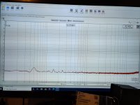
Also replaced the AD8228 with the AD8421 and build the attached "cold resistor". Still need to mount those. When all is up and running I'll post some measurements.
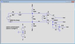
The OPA1656 seems to offer the best performance in the cold resistor circuit of all op-amp's I simmed (quite a lot of them), still not really sure what parameter is most critical for the noise performance in this application. Any toughts?
The cold resistance circuit has a resistance of about 47 kohm to ground while everything else is balanced, so it isn't clear to me either how you are going to connect it. If it was 23.5 kohm to ground, you could make two of them per channel and connect one to each side.
I expect that the circuit will be more accurately 47 kohm without R2 and C6. If the 2.21 Mohm resistor R6 is a through-hole resistor, it will probably have enough parasitic capacitance to compensate for the pole caused by C5 anyway.
Regarding op-amps, the purpose of the cold resistance circuit is to get rid of the 0.5869 pA/sqrt(Hz) noise current of a 47 kohm termination resistor at room temperature. When you use an NE5534A, it injects 0.4 pA/sqrt(Hz) of noise current of its own, which will reduce the efficacy. Low-noise FET op-amps should work well.
With Sallas measurements and observations on NE5534 vs LM833, the E.F Taylor idea might be a winning idea for the simplest phono preamp with sufficient overload margins and noise.Common mode distortions are perceived as noise in the end...I don't think people are annoyed more by white noise which is the exact perception of the current noise of usual bipolar op-amps driven by high impedance sources.
Mark,
You are making things too complex IMO.
The get the cooled resistor function, all you have to do is to insert two resistors from the output of your AD8421 to the input, no further amps needed.
I don't know what overall gain you have, but I have guessed a 20dB gain up to your ADC.
In that case you would need two 522k resistors to get an improvement in S/N of 3.4dBA.
That's about the maximum you can get.
Hans
Attachments
The cold resistance circuit has a resistance of about 47 kohm to ground while everything else is balanced, so it isn't clear to me either how you are going to connect it. If it was 23.5 kohm to ground, you could make two of them per channel and connect one to each side.
I expect that the circuit will be more accurately 47 kohm without R2 and C6. If the 2.21 Mohm resistor R6 is a through-hole resistor, it will probably have enough parasitic capacitance to compensate for the pole caused by C5 anyway.
Regarding op-amps, the purpose of the cold resistance circuit is to get rid of the 0.5869 pA/sqrt(Hz) noise current of a 47 kohm termination resistor at room temperature. When you use an NE5534A, it injects 0.4 pA/sqrt(Hz) of noise current of its own, which will reduce the efficacy. Low-noise FET op-amps should work well.
Hi Marcel,
1 input is grounded, so the attached cold resistor is between the signal and ground. It works fine in sims, reducing the noise a bit. Was just wondering what makes the OPA1656 so good at this application.
Mark,
You are making things too complex IMO.
The get the cooled resistor function, all you have to do is to insert two resistors from the output of your AD8421 to the input, no further amps needed.
I don't know what overall gain you have, but I have guessed a 20dB gain up to your ADC.
In that case you would need two 522k resistors to get an improvement in S/N of 3.4dBA.
That's about the maximum you can get.
Hans
Hi Hans, that could very well be the case. It's a learning experience this, and fun to do.
Gain in the inamp is 40dB, gain in the opa1632 stage is -6dB.
I didn't consider this option, very elegant. And I think you agree getting more s/n for the cost of just 2 resistors is not a bad trade-off?
Actually from a diy point of view, I don't mind spending a couple of euro's on OPA1656 and a couple of resistors and capacitors.
After all this effort, don't you think a classic all in one phono preamp would have been much simpler, safer, better and cheaper? I can apperciate the effort and perseverance in trying something new but vinyl is anything but new...I found E.F Taylor system so simple and effective that the only other option i can consider now is tube preamps... but i think that phono systems can't be imagined without high power amplifiers if you want to preserve the whole dynamic plus noise, click and pops. Any guitar player knows that the best sound is obtained theough miking technique because of the slew rate limiting factor added by the speaker and microphone itself let alone the use of a real compressor after that. Usually the best high end systems with phono are nothing but very high dynamic phono preamps followed by very high power amplifiers and speakers and nothing else... When trying to get into an ADC the ADC may have huge dynamic range and SNR, but his noise floor starts 60..70 db below the phono level so you add the phono system noise and dynamic to that and you simply find that there's no ADC on the market able to capture the full vinyl dynamic unless noise reduction systems and slew rate killers or dynamic compression are used. I know not everybody agrees with me, but using Audacity is just another effect aimed at tricking your ears, not a real system able to preserve the full phono dynamic riding the vinyl noise. Calculating the phono preamp noise itself is just useless when dealing with dust and i think i said it too often to be credible.Having huge overload limits of a phono preamp getting into an ADC is again the wrong path because you're going to saturate the ADC unless controlled soft clipping or compressors are used. I'd look for a real professional compressor before any ADC when dealing with phono preamps especially if i'm going to use riaa in DSP after the ADC. Modern compressors are much lower THD than the cartridge itself and they can't do anything wrong. I can remember that there was a VK-7 compressor-noise reduction system schematic on the internet a while ago, but it dissapeared or at least i am unable to find it now but now we have some very good compressor chips available... Design Notes for THAT ICs
Hi dreamth,
I don not agree with all you are saying here, but I think you're also missing the point of this project a bit.
This was never about the most economical solution, this is about having fun, using parts that I already had (dsp), learning while doing, and getting into Vinyl. That in itself is not about the absolute sound quality, it's the experience. Getting a record out and clean, putting it on, not being able to skip thrue a million tracks and so on.
In the end it's just all good fun to get this up and running, and also end up with something that measures and in extension sounds good.
Hi Mark,Gain in the inamp is 40dB, gain in the opa1632 stage is -6dB.
I didn't consider this option, very elegant. And I think you agree getting more s/n for the cost of just 2 resistors is not a bad trade-off?
Actually from a diy point of view, I don't mind spending a couple of euro's on OPA1656 and a couple of resistors and capacitors.
Now that I now the exact gain, I did the calculation again and since one leg of you inamp is grounded, you only need one single 2.38Meg resistor from the AD8421's Ref side to the input.
Riaa processed and A-Weighted S/N improvements with the two cold resistor alternatives are a remarkable:
2.38Meg Resistor: 4.45dBA
Dual OPA1656: 4.08dBA
Hans
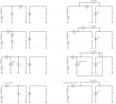
There are at least three reasons why Hans's cold resistance is better than the separate cold resistance circuit:
1. The circuit is much simpler
2. It reduces the conversion from voltage to current noise that you get when you transform the amplifier's voltage noise from after to before the termination resistor, see the attachment
3. It doesn't have the extra noise sources from the op-amps
1. The circuit is much simpler
2. It reduces the conversion from voltage to current noise that you get when you transform the amplifier's voltage noise from after to before the termination resistor, see the attachment
3. It doesn't have the extra noise sources from the op-amps
Attachments
Hi Mark,
Now that I now the exact gain, I did the calculation again and since one leg of you inamp is grounded, you only need one single 2.38Meg resistor from the AD8421's Ref side to the input.
Riaa processed and A-Weighted S/N improvements with the two cold resistor alternatives are a remarkable:
2.38Meg Resistor: 4.45dBA
Dual OPA1656: 4.08dBA
Hans
Hi Hans,
Thank you for this! So the resistor from the ref output of the inamp to the positive input of the inamp.
I'm really tempted now to hack in a 2.21M resistor, already have those...
Actually, thinking about it. The only reason I grounded the negative input of the inamp input is to provide a DC path it needs, so with this configuration it could be fully differential again! Very tempting...
Last edited:
Mark,
One other trick that you may like to implement for your Single ended cold resistor.
Split the high ohmic cold resistor in two parts, one 47K and one of the original value minus 47K, whereby the 47K should be connected to the Cart side.
Now when grounding the junction of the 47K and the high ohmic cold resistor, you go to a non cold resistor situation and after relieving you have your cold resistor back again.
By switching this way on and off you can simply check what the effect of the cold resistor is.
Hans
Last edited:
There are at least three reasons why Hans's cold resistance is better than the separate cold resistance circuit:
1. The circuit is much simpler
2. It reduces the conversion from voltage to current noise that you get when you transform the amplifier's voltage noise from after to before the termination resistor, see the attachment
3. It doesn't have the extra noise sources from the op-amps
Hi Marcel, yes it is really a very elegant solution, like it a lot.
Both your help is very much appreciated, you're miles ahead in analog design. Real shame there was next to no focus on analog design when I was attending the MTS and HTS.
Learning a lot now!
- Status
- This old topic is closed. If you want to reopen this topic, contact a moderator using the "Report Post" button.
- Home
- Source & Line
- Analog Line Level
- Overload margin in Phono pre-amp