Hey everyone, I'm a recent graduate from electrical engineering and I want to start working my way into the audio field.
I want to create a passive analog summing mixer with 16 balanced inputs and 2 balanced outputs to use in my personal studio. Basically all mixing and panning is done ITB, summed through this mixer, and then amplified by a mic preamp to make up for the attenuation loss. It's a simple concept and a very easy design for me to take on since this is my first.
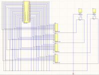
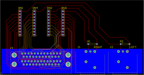
I'm not very concerned with the schematic design or functionality, but I have little to no experience creating PCB layouts. Especially in the audio realm where things may be done differently. I was wondering If someone could take a look at this layout and review it and offer suggestions/improvements.
Some general questions I have:
Grounding. I've seen a million different opinions on what to use, and I have ZERO expertise on the subject (star vs plane etc.). Would one of these be better for my specific design? How do I implement it in the most effective way? If I can use ground plane (like I am currently), what area should it cover?
Routing. The dualport dsub killed me. Is it ok to use multiple layers in a design like this? How could I improve my routing? Is 10mil okay for trace width?
Are the placement of my connectors ok? (CAD is not my strength, and I want to be able to use an enclosure properly)
A few things to note:
I want all connectors to be rear facing, so there will be some unavoidable black space (upper right). That's ok with me.
I want to use the dualport dsub connector for the inputs in order to save the most space, even though it makes routing a nightmare.
It honestly blows my mind that I can go through 4 years of electrical engineering and have zero experience working with any kind of PCB design in classes or labs. Thank you for any help, suggestions or ideas, it's been nearly impossible to find this kind of info anywhere.
I want to create a passive analog summing mixer with 16 balanced inputs and 2 balanced outputs to use in my personal studio. Basically all mixing and panning is done ITB, summed through this mixer, and then amplified by a mic preamp to make up for the attenuation loss. It's a simple concept and a very easy design for me to take on since this is my first.
I'm not very concerned with the schematic design or functionality, but I have little to no experience creating PCB layouts. Especially in the audio realm where things may be done differently. I was wondering If someone could take a look at this layout and review it and offer suggestions/improvements.
Some general questions I have:
Grounding. I've seen a million different opinions on what to use, and I have ZERO expertise on the subject (star vs plane etc.). Would one of these be better for my specific design? How do I implement it in the most effective way? If I can use ground plane (like I am currently), what area should it cover?
Routing. The dualport dsub killed me. Is it ok to use multiple layers in a design like this? How could I improve my routing? Is 10mil okay for trace width?
Are the placement of my connectors ok? (CAD is not my strength, and I want to be able to use an enclosure properly)
A few things to note:
I want all connectors to be rear facing, so there will be some unavoidable black space (upper right). That's ok with me.
I want to use the dualport dsub connector for the inputs in order to save the most space, even though it makes routing a nightmare.
It honestly blows my mind that I can go through 4 years of electrical engineering and have zero experience working with any kind of PCB design in classes or labs. Thank you for any help, suggestions or ideas, it's been nearly impossible to find this kind of info anywhere.
Attachments
What's the source impedance? Signal levels? Load impedance? If its all low impedance a groundplane is probably simplest. With all differential signals ground loops aren't a big issue anyway.
No need to go down to 10mil traces where there's room for thicker, its not a logic board, not that it will make any difference.
No need to go down to 10mil traces where there's room for thicker, its not a logic board, not that it will make any difference.
Hope You have seen this
How to Build a DIY Passive Summing Box – DIY Recording Equipment
If it's a metal box, PIN1 should go to chassis and not to the PCB. (Pin1 dilemma), then just a wire to connect The PCB ground.
I would use a ground plane covering the whole PCB as You intend to use low signals.
What's the purpose of the two resistors ?
The signals are all balanced line level coming out of an audio interface with low impedance, and the output would be to a mic preamp. The load impedance will be about the same as the input impedance of the summing mixer (6.8k), as are the source and output impedances (180 ish).What's the source impedance? Signal levels? Load impedance? If its all low impedance a groundplane is probably simplest. With all differential signals ground loops aren't a big issue anyway.
No need to go down to 10mil traces where there's room for thicker, its not a logic board, not that it will make any difference.
Thanks for the advice, are there typical/ideal trace sizes for audio signals?
Funny that you linked that page, I based my design around the info I found there!Hope You have seen this
How to Build a DIY Passive Summing Box – DIY Recording Equipment
If it's a metal box, PIN1 should go to chassis and not to the PCB. (Pin1 dilemma), then just a wire to connect The PCB ground.
I would use a ground plane covering the whole PCB as You intend to use low signals.
What's the purpose of the two resistors ?
Since you mentioned it, I'm really hoping you can help me understand this. I see mention of chassis grounding whenever I look up grounding related to audio. And it makes sense to me theoretically. But I have yet to find any info on HOW to actually implement this in a real design. Would I literally be soldering a wire from pin1 to the chassis? and then how should that connect to the PCB ground plane? I've been looking for these answers for a while, and I haven't had any luck so far.
Those resistors are shunt resistors that help set the output impedance of the device. There's a formula I used that can be found on the page you linked that factors in the number of inputs, input impedance and desired output impedance.
You solder a wire from each PIN1 to the chassis. Use the fixing bolt for example.
You then solder a wire from the ground plane to a bolt on the chassis.
Or .. solder all 1's together and then a wire to the chassis. That's what most folks do.
Try what works best in Your situation.
You then solder a wire from the ground plane to a bolt on the chassis.
Or .. solder all 1's together and then a wire to the chassis. That's what most folks do.
Try what works best in Your situation.
Pin 1 RevisitedFunny that you linked that page, I based my design around the info I found there!
Since you mentioned it, I'm really hoping you can help me understand this. I see mention of chassis grounding whenever I look up grounding related to audio. And it makes sense to me theoretically. But I have yet to find any info on HOW to actually implement this in a real design. Would I literally be soldering a wire from pin1 to the chassis? and then how should that connect to the PCB ground plane? I've been looking for these answers for a while, and I haven't had any luck so far.
Those resistors are shunt resistors that help set the output impedance of the device. There's a formula I used that can be found on the page you linked that factors in the number of inputs, input impedance and desired output impedance.
As for the practical assembly, a lot of it will depend on the type of connectors that you use. Neutrik has certain models of connectors with metal bodies bonded to pin 1 out of the box, so as long as you get a good mechanical connection with the chassis (sometimes easier said than done), you're already there.
Last edited:
I use stainless steel star washers for good contact to sheet metal case: https://www.grainger.com/product/FABORY-Lock-Washer-23NJ71?
the one linked to is a #8 internal tooth. Obviously it is for use with #8 machine screws & nuts.
Factories in the appliance business can buy brass star washers for grounding screws in pallets of boxes of 50 lb from vendors like ITW. But you can't buy small quantities of the brass star washers.
You can also use the star washer for screwing a ring crimp terminal on a wire to a ring land on a pcb.
You could really get an education in how things are done by taking apart dead appliances.
Last edited:
Yep. Also really good are the serrated safety washers.I use stainless steel star washers for good contact to sheet metal case: FABORY Lock Washer, Bolt '#'8, 18-8 SS, PK50 - 23NJ71'|'U51460.016.0001 - Grainger
the one linked to is a #8 internal tooth. Obviously it is for use with #8 machine screws & nuts.
Safety Washers Type „S” - Schnorr GmbH
Serrated Safety Washers - Springmasters
One used in a bolted joint, if selected and installed properly, will provide a long-lasting gas-tight bond. The teeth in a star washer also provide some preload although probably to a lesser degree than a safety washer or a spring washer (Belleville).
EDIT: Of course, if you're looking for a "forever" bond, this might be right up your alley. YouTube
Last edited:
So I've been looking around and found these XLR connectors here: NC3MAAH-1 | Neutrik
They have ground connection built in from PIN1 to chassis via the connector shell which prevents me from having to solder a wire myself. My question is now how you would recommend connecting the ground plane? In my current design, PIN1 is directly connected to the ground plane by the via, but with this specific part that would make the ground plane and chassis directly connected with PIN1 being the common node. Is better to disconnect PIN1 from ground plane and instead solder from some point on the ground plane to the chassis?
They have ground connection built in from PIN1 to chassis via the connector shell which prevents me from having to solder a wire myself. My question is now how you would recommend connecting the ground plane? In my current design, PIN1 is directly connected to the ground plane by the via, but with this specific part that would make the ground plane and chassis directly connected with PIN1 being the common node. Is better to disconnect PIN1 from ground plane and instead solder from some point on the ground plane to the chassis?
Pin 1 of xlr is a RF shield. Not for signal use. Goes to braided wrapper of coax TP cable. Case is a safety ground required by UL/VDE/CE etc etc. Case should go to safety pin of line cord, where it picks up all sorts of switching transients from the motors & SMPS in the building. Pin 1 should connect to case.
2 & 3 are differential TP signal use. 2 & 3 should go to + & - inputs of an op amp for best common mode hum rejection. Or an audio transformer.
IC analog ground should be separated from safety ground by a ~1 to 10 ohm resistor parallel ~.1 uf cap parallel two back to back diodes with sufficient current handling capability to carry a short from the power transformer to safety ground.
Peavey doesn't use ground planes on PCB in the products I have. there might be a good reason, since they had so much market share in the 80's-90's. Rebuilt Peavey products have less hum than the products I build at home.
Suggest you read "grounding & shielding in instrumentation" book I found on closeout shelf of a bookstore in 1970. Secret knowledge not taught in colleges because there is not enough math to flunk any students with.
Last edited:
Agreed, pin 1 should go to the chassis. However, for the NC3MAAH-1, it does not have pin 1 connected to the shell/panel... in fact, none of Neutrik's male XLR connectors do (only the female ones do, specifically the ones numbered with "1" and not "2" - see page 41 below)Pin 1 of xlr is a RF shield. Not for signal use. Goes to braided wrapper of coax TP cable. Case is a safety ground required by UL/VDE/CE etc etc. Case should go to safety pin of line cord, where it picks up all sorts of switching transients from the motors & SMPS in the building. Pin 1 should connect to case.
https://www.neutrik.com/media/10098/download/product-guide---section-xlr.pdf?v=3
Also, balanced cable should be twisted pair, not coax, unless you mean the shield is (sort of) coaxial with the signal conductors.
Why? Is this a reference to a ground loop breaker circuit, commonly used to reduce ground loop effects in single-ended connections?IC analog ground should be separated from safety ground by a ~1 to 10 ohm resistor parallel ~.1 uf cap parallel two back to back diodes with sufficient current handling capability to carry a short from the power transformer to safety ground.
Pin 1 of xlr is a RF shield. Not for signal use. Goes to braided wrapper of coax TP cable. Case is a safety ground required by UL/VDE/CE etc etc. Case should go to safety pin of line cord, where it picks up all sorts of switching transients from the motors & SMPS in the building. Pin 1 should connect to case.
2 & 3 are differential TP signal use. 2 & 3 should go to + & - inputs of an op amp for best common mode hum rejection. Or an audio transformer.
IC analog ground should be separated from safety ground by a ~1 to 10 ohm resistor parallel ~.1 uf cap parallel two back to back diodes with sufficient current handling capability to carry a short from the power transformer to safety ground.
Peavey doesn't use ground planes on PCB in the products I have. there might be a good reason, since they had so much market share in the 80's-90's. Rebuilt Peavey products have less hum than the products I build at home.
Suggest you read "grounding & shielding in instrumentation" book I found on closeout shelf of a bookstore in 1970. Secret knowledge not taught in colleges because there is not enough math to flunk any students with.
So I can keep the PIN1 to chassis and signal ground completely separate and that's ideal? As illustrated in the picture attached.
What about the DB25 then? There are essentially 16 balanced inputs (positive, negative, ground). Should the grounds of this connector be treated the same way (to chassis)?
Attachments
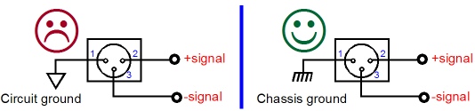
Yes, pin 1 should be connected to chassis as close as possible to the entry point, and should not be connected to signal "ground" (0V or common), but keep in mind that signal ground, somewhere inside your enclosure, will be connected to earth/safety ground/PE/chassis/etc. (pick one) somewhere.So I can keep the PIN1 to chassis and signal ground completely separate and that's ideal? As illustrated in the picture attached.
See heading "Chassis Ground vs. Signal Ground" and Figure 4 in the below:
Grounding and Shielding Audio Devices
Same thing, connect them to chassis as close as possible to the input connector. You can daisy-chain/bridge these ground conductors with a thick, low-impedance conductor if it's easier for you.What about the DB25 then? There are essentially 16 balanced inputs (positive, negative, ground). Should the grounds of this connector be treated the same way (to chassis)?
Last edited:
Same thing, connect them to chassis as close as possible to the input connector. You can daisy-chain/bridge these ground conductors with a thick, low-impedance conductor if it's easier for you.
Makes sense. Interestingly enough, this circuit appears to have no signal ground then... The only "grounds" in this device are the PIN1's of the DB25 inputs and XLR outputs. Is that normal?
So... without a signal ground, could I simply connect all the PIN1's together and then connect them to chassis at one point?
You don't have a signal ground in a typical balanced XLR interconnect cable either.Makes sense. Interestingly enough, this circuit appears to have no signal ground then... The only "grounds" in this device are the PIN1's of the DB25 inputs and XLR outputs. Is that normal?
So... without a signal ground, could I simply connect all the PIN1's together and then connect them to chassis at one point?
Yes to the latter question, as long as you're reasonably close to the entry connector.
The RN's are just bussed resistor networks. They're 8 resistors that output to one pin. There are 16 balanced inputs from the dual DB25, broken up into left/right channels (8 stereo pairs). Each stereo channel then has one bussed resistor for the hot pins and one for cold pins, hence 4 total resistor networks.Maybe I'm not understanding something, what's the purpose of RN1 through RN4? And what does ITB mean (for you)?
By ITB, I mean I mix all my audio as though I normally would (including panning) digitally in a DAW. My audio interface will have 16 analog outs via an identical DB25. I group tracks and assign outputs in my DAW and then send them to my summing mixer, and then record the output as the printed mix.
Could you not do the summation in your DAW then and skip all the external work?The RN's are just bussed resistor networks. They're 8 resistors that output to one pin. There are 16 balanced inputs from the dual DB25, broken up into left/right channels (8 stereo pairs). Each stereo channel then has one bussed resistor for the hot pins and one for cold pins, hence 4 total resistor networks.
By ITB, I mean I mix all my audio as though I normally would (including panning) digitally in a DAW. My audio interface will have 16 analog outs via an identical DB25. I group tracks and assign outputs in my DAW and then send them to my summing mixer, and then record the output as the printed mix.
- Status
- This old topic is closed. If you want to reopen this topic, contact a moderator using the "Report Post" button.
- Home
- Source & Line
- Analog Line Level
- Passive Analog Summing Mixer Design Review