I've been having fun today trying them out with my ACP+ and Grado 325s. You can hear a difference with one in circuit. The difference with two is even better. Lots and lots of extra musical details. Spatial positioning of instruments is truly excellent. Now I just need to get a case and then try it through my main system.
Second opinion from SWMBO, "It's like putting your glasses on, it brings things into focus."
This afternoon's project is to try them out on the Starving Student II and, if time allows, the B1K in the office system.
I hope that you all enjoy them too.
Second opinion from SWMBO, "It's like putting your glasses on, it brings things into focus."
This afternoon's project is to try them out on the Starving Student II and, if time allows, the B1K in the office system.
I hope that you all enjoy them too.
This is very interesting. I tried to make a filter like this with inductors I pulled out of a switching power supply. It did attenuate the noise, but not nearly enough. It made a slight improvement but the headphone amp clearly sounded better with an old fashioned wall wart powering it.
I was wondering if the circuit could be scaled. For line level circuits and class AB headphone amps I was thinking of using 0.4 ohm or 1 ohm series resistors. It sure would be handy to use some of these laptop supplies for audio projects.
Inductors out of stock https://www.mouser.com/ProductDetai...lpSb4997bEggmakl8oA85JEUfegT39YzqdHBdHMSEZA== but they're affordable and not too big.
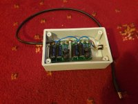
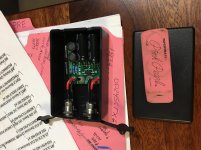
Just about as small as can go...
Boxes:
LeMotech 5 Pieces Plastic Project Box es Junction Case for Electronic Project, Black 3.15 x 1.97 x 1.02 inch (80 x 50x 26 mm)
Jack’s:
5.5 x 2.1 MM 10A DC Power Jack Socket Dc099 30V Threaded Female Mount Connector Adapter with 3.94 Ich 18AWG Cable and DC Barrel Jack Plug Male Lsgoodcare
Siliconed board to box.
Attachments
Last edited:
kasey197 said:These are awesome ! I also enjoyed the company of a super simple (standard 5 component) cap multiplier after the passive filter ...
Excellent! Please tell members here the voltage dropped (the reduction) from input to output of your cap multiplier, so they can decide whether it would be acceptable in their own application.
You might also consider uploading the Gerber files of your design, so that other builders can order PCBs and try it out for themselves.
Hi Mark,
Small question...
I can see the benefit of multiple filtering daisychaining several of your excellent filters, connecting them in series.
Now, would it also make sense to plug them in parallel (say 2 of them),to increase current rate from say 3A to 6A?
Or is there a downside joining their outputs together - I guess not given the output filtering caps, but then...
I know you have something much more dedicated in progress for extra current, I was just wondering if "meanwhile" this could be worth a try.
Thanks again
Claude - trying to make good use of his 10 filters")
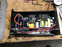
In the interest of science I had to try two filters in parallel. I also wanted to measure with and without load. The filter clearly performs much better with light load.
The power supply is the cheap brick that is delivered together with the Aiyima TPA3251.
First picture is one filter without load. Second one is two filters in parallel approx 1 A load and finally one filter and 1 A load.


You'll need to make sure the load current drawn from the SMPS is the same in all cases -- so the SMPS output noise is the same in all cases.
When you draw zero current from the filter (first picture) you need to draw 1A from the SMPS, by connecting your load resistor at the SMPS output, before the filter.
When you draw zero current from the filter (first picture) you need to draw 1A from the SMPS, by connecting your load resistor at the SMPS output, before the filter.
Mark, you are absolutely right about the same conditions should apply, but my interest is more of a "what if" nature.
I have made new measurements. 1A load at the input of the filters and 50mA load at the output of the filters. Without any load besides the scope the damping is slightly better but not that much.
As far as I see, the filter works better (higher damping) the less load that is applied on it. Worst case scenario for the filter is a class A amplifier, but it might still of some use.
I really can't see that much difference with two filters in parallel so next step is to try it out on my TPA3255EVM.
First picture is one filter and the second picture is of two filters in parallel.
Yep konst, serial daisy chaining is of course fine. Brought a benefit on some occasions, on others 1 filter did already an outstanding job. Doesn't increase the max Ampere limit though, something parallel filters can address... question is how good are they then, that is while waiting for Mark's dedicated 6A solution which is likely to settle it all...
Have fun
Claude
Have fun
Claude
I've been thinking about how best to test the filter's effectiveness and I think o-scope measurements are only part of the equation since there are different smps switching frequencies and different o-scope setups (bw, probes, risetime, etc..). What really matters is the noise in the audio band. I think the psu+filter coupled to an ADC with a reasonably sized capacitor to block DC and ploting the spectrum with a waterfall graph will show the noise that really matters? I should be able to try this out tomorrow and I'm curious if anyone else has done something similar with the filter?
Don't believe it has been already reported... Sounds like something nice to try!
Would though have extented to over 20kHz if you can. Understand the rational behind, but IME some audio gear is sensitive to perturbations with frequencies well over the audioband... that do reflect in something bad to our ears (in the audioband).
Let us know
Claude
Would though have extented to over 20kHz if you can. Understand the rational behind, but IME some audio gear is sensitive to perturbations with frequencies well over the audioband... that do reflect in something bad to our ears (in the audioband).
Let us know
Claude
At SMPS frequencies you start getting into Signal Integrity engineering, and need to employ best practices when building test fixtures and connecting measuring equipment.
One way to get a "quick peek" at how terrible your setup might be, is to connect the SMPS, filter, and load resistor, so the SMPS is supplying power to the load. Then display the waveform of GROUND at the filter output. In theory it should be a horizontal flat line with zero millivolts of noise superimposed. In practice it almost never is, unless you've carefully designed your fixtures to have zero inductance ground planes, and used RF cables with SMB or BNC connectors, everywhere.
One way to get a "quick peek" at how terrible your setup might be, is to connect the SMPS, filter, and load resistor, so the SMPS is supplying power to the load. Then display the waveform of GROUND at the filter output. In theory it should be a horizontal flat line with zero millivolts of noise superimposed. In practice it almost never is, unless you've carefully designed your fixtures to have zero inductance ground planes, and used RF cables with SMB or BNC connectors, everywhere.
- Home
- Source & Line
- Analog Line Level
- PO89ZB , an inline DC filter for SMPS wall warts . Preamps, HPA, Korg NuTube, etc