Thanks Kasey
Do you perhaps have a schematic showing how you connected both SMPS at the input/main and at the output?
I had a look at the Mean Well you mentioned. My knowledge of SMPS is limited. My understanding is it might be feasible on some to connect + of one unit with - of the other to form the ground / amp 0V.
I would have thought though it depends on the technology used for the SMPS and would per definition only apply if not connecting any part of the SMPS to ground, that is having only on the side of the mains L and N connected with 120 or 240V AC depending on the country... and no ground.
Is that correct?
If so, how to ground the units? I know my old amps only have L and N but when dealing with a big Class A or AB amp with heavy dual voltage (say +40 and -40V and over 10A per phase and channel) I guess knowadays people would for safety reason have a ground at the mains?
Thanks again for your help, SMPS could open a brand new field of possibilities, if only it were quality dual phase...
Claude
Re coils, mine are due in 2 weeks, and (chicken, I know...) I perfered to stick to what I knew and was recommanded. Enough variables and risks running my company - when dealing with hobbies they have to be quite straightforward ")
Plus I would probably have the parts lying around, in time indeed but me not being available LOL - what are 2 extra weeks on MY audio projects?
Will though introduce a new variable in form of the latest caps... and report
Claude
Plus I would probably have the parts lying around, in time indeed but me not being available LOL - what are 2 extra weeks on MY audio projects?
Will though introduce a new variable in form of the latest caps... and report
Claude
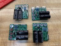
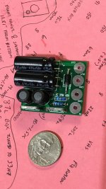
I ordered the boards from JLPCB. It couldn't be any easier. Got them in a week or so.
Components came from Mouser. Yes, the coils are on back order, but I'm in no hurry. Figured I'd just get all the components on the same BOM as opposed to a Mouser/Digi Key split order.
It's easy to add the components and you can complete a board in 5-10 minutes.
Components came from Mouser. Yes, the coils are on back order, but I'm in no hurry. Figured I'd just get all the components on the same BOM as opposed to a Mouser/Digi Key split order.
It's easy to add the components and you can complete a board in 5-10 minutes.
Attachments
Fwiw, here are some interesting measurements from stereophile between amps using linear vs smps supplies for your enjoyment.
Not at all a scientific comparison, but it seems at least plausible that some of the differences are due to the use of switching supplies.
This is a also a nice five min watch: Audio Myth - "Switching Power Supplies are Noisy" - Benchmark Media Systems
On another thread i also did measurements on some supplies and the effects of a SMPS filter..I didn't know at the time that there was already a project cooking on this else i'd have waited for an expert designed one! I'm really looking forward to trying out the design from Mark when its published!
post #41:
Mean well vs generic power adapter vs audio oriented smps
Cheers,
The Benchmark video is advertising and it is also not exactly the standard cheap SMPS as generally found.
What often seems to be forgotten is the pollution many SMPS produce at the mains side of things. And the RF emission .... the short life of many of them ... the wearing out of caps at the higher frequencies... the wining noise they often make ....
It is like class D, when that started people were complaining of cold sound, non musical blah blah. Nowadays class D is the new standard according to many
The details are somewhat forgotten like lower weight when shipping from China, very little or no costly heatsink....
Last edited:


konst, your filter scope trace looks really good - I don't think you had a cursor on the pre filter trace, but eyeballing it looks like ~120mV pk-pk on the burst and 8.8mV from the cursor on the post-filter? If so that's ~23dB, really good. I put a 40% load on psu and ended up ~14dB so I'm missing 9dB in a good layout!

Last edited:
I have a construction question
Is there a maximum length for the output cable of the filter ?
I guess what I want to know is , after the filter does its magic , if I had a 4-5 foot cable to connect to the back of my B1 Korg would the long cable re-introduce noise into the signal ?
Is there a maximum length for the output cable of the filter ?
I guess what I want to know is , after the filter does its magic , if I had a 4-5 foot cable to connect to the back of my B1 Korg would the long cable re-introduce noise into the signal ?
Hi Mark,
Small question...
I can see the benefit of multiple filtering daisychaining several of your excellent filters, connecting them in series.
Now, would it also make sense to plug them in parallel (say 2 of them),to increase current rate from say 3A to 6A?
Or is there a downside joining their outputs together - I guess not given the output filtering caps, but then...
I know you have something much more dedicated in progress for extra current, I was just wondering if "meanwhile" this could be worth a try.
Thanks again
Claude - trying to make good use of his 10 filters
I cleaned up a few things on my hacked together version of the filter and refined the measurements. I'm getting ~26dB attenuation on the the 100kHz pulse train.

I did a quick sim and it looks like the filter design is aproximately -22dB/octave above 2kHz. I included the coil DCR and cap ESR but not all the parasitics.

konst is sending me a couple boards - thank you very much!
The design has basically no insertion loss, is simple, low cost and has great attenuation.
I did a quick sim and it looks like the filter design is aproximately -22dB/octave above 2kHz. I included the coil DCR and cap ESR but not all the parasitics.
konst is sending me a couple boards - thank you very much!
The design has basically no insertion loss, is simple, low cost and has great attenuation.
- Home
- Source & Line
- Analog Line Level
- PO89ZB , an inline DC filter for SMPS wall warts . Preamps, HPA, Korg NuTube, etc