Mark, sorry to come so late to the party, I think this is a very sensible addition to our tool collection!
For some of my more sensitive measurements I often have to resort to using a Powerbank, but this little thing might make it unnecessary.
I didn't read the whole thread, but did you publish any measurements or an LTspice file for this?
Jan
For some of my more sensitive measurements I often have to resort to using a Powerbank, but this little thing might make it unnecessary.
I didn't read the whole thread, but did you publish any measurements or an LTspice file for this?
Jan
Hi Jan, no I haven't published measurements or LTSPICE files. A couple of builders uploaded before-and-after oscilloscope photos, showing time domain behavior, and it looks quite pleasing. Anecdotally.
A quick calculation of the filter's input impedance might suggest how easy or how difficult it could be, to take physical measurements of its frequency domain behavior.
Thus, lacking rigorous data, this PCB and project is merely a very inexpensive "try it yourself and see what YOU think" little audio board.
If you, or anyone else, wants to create an LTSPICE simulation of PO89ZB, starting from a blank sheet of paper, you'll need to obtain six constants. Either by digging through datasheets, or doing a little EE math, or measuring actual parts, or a combination of the above.
Several of these are discussed in depth, in the citations presented in post #9 above.
Once you've created a simulation that you trust, you can do some "sensitivity analysis" to discover which of the six constants above, have the greatest effect upon the filter's behavior. Maybe you'll find out that a couple of them have comparatively small effect; varying them by +/- 25% only changes the filter behavior by +/- 3%, for example. Then you can berate and bitterly reproach yourself for working so very hard to get a semi precise estimate of those constants, when in reality a rough guess would have worked equally well. Or maybe you'll find that there are no low-sensitivity constants and hard work has paid off handsomely, every time.
_
A quick calculation of the filter's input impedance might suggest how easy or how difficult it could be, to take physical measurements of its frequency domain behavior.
Thus, lacking rigorous data, this PCB and project is merely a very inexpensive "try it yourself and see what YOU think" little audio board.
If you, or anyone else, wants to create an LTSPICE simulation of PO89ZB, starting from a blank sheet of paper, you'll need to obtain six constants. Either by digging through datasheets, or doing a little EE math, or measuring actual parts, or a combination of the above.
- The series resistance of each inductor
- The (parasitic) parallel capacitance of each inductor
- The inductance of each inductor
- The equivalent series resistance of each capacitor ("ESR")
- The equivalent series inductance of each capacitor ("ESL")
- The capacitance of each capacitor
Several of these are discussed in depth, in the citations presented in post #9 above.
Once you've created a simulation that you trust, you can do some "sensitivity analysis" to discover which of the six constants above, have the greatest effect upon the filter's behavior. Maybe you'll find out that a couple of them have comparatively small effect; varying them by +/- 25% only changes the filter behavior by +/- 3%, for example. Then you can berate and bitterly reproach yourself for working so very hard to get a semi precise estimate of those constants, when in reality a rough guess would have worked equally well. Or maybe you'll find that there are no low-sensitivity constants and hard work has paid off handsomely, every time.
_
Last edited:
"ESR 0.045" means 45 milliohms of equivalent series resistance
"ESR 0.030" means 30 milliohms of equivalent series resistance
"ESR 0.015" means 15 milliohms of equivalent series resistance
OK - now I see them - I had to scroll sideways to se the numbers after the dot. Missed that scrolling - sorry!
How about those SMD resistors - can they be OK?
//
LOL!
In doubt I go for the latter option... and trust clearly Mark for knowing what he is doing.
This unit works great as it is, more than just the sum of its components.
Mark, the next 8 filters I will build shortly will be with your latest recommendation, that is Nichicon 25mm caps.
I shall be able to compare the new filters to the old ones and, having little doubt on your advice, will also have some extra caps on hand... to be able to retrofit them to my older filters.
Mark, seeking for the best, do you think it is OK to replace your recommended coils (which worked so well) with the Wurth ones, or am I best of relaxing and waiting for Feb that Mouser gets the original ones back in?
https://www.mouser.fr/ProductDetail/Wurth-Elektronik/744772022?qs=VxkwJfKV0FR%2Bdd5lAI5lGQ==
I will follow your recommendation blindly, going exactly for what you designed. Again time is not a real issue, but "while at it" if I can build the filters around Xmas my kid will enjoy an electronic project ;-)
Many thanks again for all your help... and continuous developme,t of this little gem
Claude
Last edited:
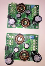
Working with a set of Beta Testers, we're trying the idea of using two commercial SMPS to power a First Watt Class A amplifier. Here are the filters we're using for the first experiment. They are rated 48 volts and 6 amperes. If you are dying of curiosity, I recommend you spend a few minutes doing the math. Calculate what RMS numbers a stereo Class A amp can drive into a pair of 8 ohm loads, when the supply current is 3 amps per channel. I'm sure someone will project these specs upon a Raspberry Pi application, too.
Different filter circuit topology for different max-current environment.
It might fail. That's what sometimes happens with experiments.
_
Different filter circuit topology for different max-current environment.
It might fail. That's what sometimes happens with experiments.
_
Attachments
Hi Mark,
Very interesting project again.
I did a quick and dirty RLC filter for a friend's class D SMPS, worked OK. Was designed to withstand 35V / 6A, one filter per amp and bi-amping.
But you clearly went a step further with your filter. You seem to want 2x72W out of the Class A amp, means you design for at least 2x 150W at PS- you want your filter to cope with 300W. Plus you have 2 coils so I presume again a 'double stage' RLC filter... I went only single stage RLC. Clever bit, I don't see a large R to cope with lot of Watts, so my guess would be that role is taken care by the coil's "inherent parasitic DC resistance" while at it...
Please let us know how it works!
Take care
Claude
PS: any time by chance for you to look into my coil question for the SMPS filter?
Last edited:
Mark, can one use these do you think?
10PCS 1206 Metal Alloy SMD/SMT Chip Resistors +-1% 1W 0.04Ohm/R 0.05Ohm/R | eBay
//
Mark, would you please care to comment on this question? Pretty please?
Much appreciated / your humble servant...
//
Parts out of stock / backordered are a fact of life. They're never going away and we hobbyists have no choice but to adapt.
One approach is to order all parts from Mouser, even though they are backordered, and simply wait. It reduces the number of different companies you buy from, and it may reduce the shipping costs, import duties, customs paperwork, delivery fees, and so on. (Not sure about that, we don't have those where I live).
Another approach is to buy the exact components which the circuit designer specified, from another source. Besides Mouser, there is also DigiKey, Element14, Farnell, Newark, Arrow, RS Online, Avnet, Jaycar, and so forth. This is what I do, myself. I pay additional shipping fees; and in exchange, I don't have to wait for backorders to be filled.
A third approach is to make an educated guess about which not-backordered parts, might perform as satisfactory substitutes. When I take this path myself, I order several different substitutes, in case one or two of them don't fit properly or don't perform properly. Sometimes none of the substitutes are successful, and I have to sit and wait for backorders to be filled, just like everybody else.
A fourth approach is to ask fellow diyAudio members to sell you a few of their extras. "Does anybody have four XYZs they would be willing to sell or trade? I'll give you QQQ Euros and/or ten 2SK170BLs, whichever you prefer"
Deciding what to do in these cases, and how to go about doing it, is part of being a hobbyist. Make your decisions and live with them. If making decisions frightens you, spend extra money and pursue several alternatives simultaneously.
Hi Jan, no I haven't published measurements or LTSPICE files. A couple of builders uploaded before-and-after oscilloscope photos, showing time domain behavior, and it looks quite pleasing. Anecdotally.
A quick calculation of the filter's input impedance might suggest how easy or how difficult it could be, to take physical measurements of its frequency domain behavior.
Thus, lacking rigorous data, this PCB and project is merely a very inexpensive "try it yourself and see what YOU think" little audio board.
If you, or anyone else, wants to create an LTSPICE simulation of PO89ZB, starting from a blank sheet of paper, you'll need to obtain six constants. Either by digging through datasheets, or doing a little EE math, or measuring actual parts, or a combination of the above.
- The series resistance of each inductor
- The (parasitic) parallel capacitance of each inductor
- The inductance of each inductor
- The equivalent series resistance of each capacitor ("ESR")
- The equivalent series inductance of each capacitor ("ESL")
- The capacitance of each capacitor
Several of these are discussed in depth, in the citations presented in post #9 above.
Once you've created a simulation that you trust, you can do some "sensitivity analysis" to discover which of the six constants above, have the greatest effect upon the filter's behavior. Maybe you'll find out that a couple of them have comparatively small effect; varying them by +/- 25% only changes the filter behavior by +/- 3%, for example. Then you can berate and bitterly reproach yourself for working so very hard to get a semi precise estimate of those constants, when in reality a rough guess would have worked equally well. Or maybe you'll find that there are no low-sensitivity constants and hard work has paid off handsomely, every time.
_
Maybe people like Würth have spice models for their inductors. I'll see if I can find something.
Jan
TNT: I don't know what the issue is with the specified resistors. Mouser.se has them in stock. The only part I had to buy from another supplier where the inductors which I found in stock at elfa.se. Or use the one Claude found.
No issues. I just wanted to understand if those smd resistors could be a substitute to the one in the BOM. Thats all.
//
Last edited:
About power consumption for Raspberry Pi, dependent on how it is used, the current filter will be sufficient. Most problem with third party power supplies (wall warts) are that they often give slightly below 5V and the Raspberry is sensitive to that.
See this page for current requirements for RPi
Power Supply - Raspberry Pi Documentation
I have tried RPi 2, 3B+ and 4 with one of my filters and only ethernet and/or Wifi connected and they worked reliably, at least for a day or so. I normally use RPi2 for my two music servers and they are up and running all the time with a filter applied.
If USB devices are needed then a powered hub should work.
The only issue with the resistors is the power dissipation with whatever current you need from your supply.
The resistors from post #1 will have better thermal resistance as SMD resistors lying on a board and you sure don´t want to get near even half their stated power dissipation.
Other than that I wouldn´t go below the value Mark suggests.
These are dampening resistors for the LC also. Pure LC-filter can make SMPS instable and this filter is supposed to be kind of generic and work with "every" SMPS out there.
Well in the spirit of experimentation (and making decisions....) I've ordered parts and boards to build 10 of these, using the Nichicon capacitors recommended by Mark and these Wurth inductors https://eu.mouser.com/datasheet/2/445/744772022-539602.pdf as found by others. Nothing on backorder so hopefully I can have a few of these built before 2021")
I don't know how good my scope will be to pick up the noise on my PC's power supplies to the soundcard and USB DAC but I'll see if I can come up with a couple of pics to show before and after. If not, just the listening impressions.
Thanks Mark for posting such an interesting filter & sharing the design.
@joensd, there are diyAudio members who lay out PCBs for sport and sometimes for pay. Poke around here and there, see if you can find somebody who is willing to give you a new layout with mounting holes too. My information could be outdated or just plain wrong, so approach these members with cautious respect, but I think @Prasi and @JPS64 and @jhofland might be possibilities.
Thanks Mark for your guidance and advice!
It´s easy enough to do a layout for myself but as I don´t need many of these I wanted to express my interest in case somebody wants to share.
It´s more sustainable doing one order than everybody cooking his own soup as we say.
I´ll probably go with breadboard and see if I really need that much more.
But as Jan pointed out, this really is an invaluable tool in times of SMPS all around us.
The question is (and I´m pretty newbiish here), how generic and how stable is this filter with all those SMPS out there.
How did you come up with these values?
Any particular literature you followed?
Jens
- Home
- Source & Line
- Analog Line Level
- PO89ZB , an inline DC filter for SMPS wall warts . Preamps, HPA, Korg NuTube, etc