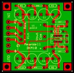
Here they are. To be clear, I am actively using the long rectangle version with a BA2018 preamp and it works well, but I have not built or tested the square version. Should be fine, but no guarantee.
Attachments
It’s too bad Mean Well doesn’t make an +/- 18V or 20V module…whether one could hear a difference between 15V or 18V input into the BA2018. I know +/- 18VDC has been described as an optimum input.
Pete
Pete
I wanted to build Wayne’s BA2018 preamp, and to save time and effort I decided to install it into my Korg B1 chassis, with a PO89ZB-based +/-15V power supply and my own pcb for delayed turn-on, relay-switched inputs, and a 12V 25mA Trigger circuit.
It all fit nicely into the 6.5” x 8.25” Korg chassis thanks especially to the PO89ZB power supply, along with a Muses chip-based IR remote controlled volume control and, surprisingly, I didn’t have to pack it in.
Sadly, it was going to be really tight to install a jack for the Trigger on the rear panel and since my current amp doesn’t have a trigger circuit, I decided to leave that capability for another project.
It’s too bad Mean Well doesn’t make an +/- 18V or 20V module…whether one could hear a difference between 15V or 18V input into the BA2018. I know +/- 18VDC has been described as an optimum input.
Pete
I agree. However there is a 24V supply if that will work. Also, here is a +-18V part, but recommends additional components on the input to meet specs, also has higher ripple and noise so I don't like it as well.
Blocked
Last edited:
Hi guys,
Not familiar with the Mean Well low power product range, but here an idea for whatever it is worth...
The LRS series I used for some power amps, that can be fitted away /remote in a casing, is very cheap and quite good in fact (and I guess Mean Well must have similar smaller power "series" for less demanding preamps?).
All LRS 24V units are in fact adjustable, down to 21.8V (actually a tad more on my units). Given there is still plenty power available, one could fit a RC filter after these SMPS to reduce voltage and have a first low Fc LP filter. Say down to 20V. From there Wapo's board, providing further voltage regulation and filtering, could be great...
Just thinking out loud...
Claude
Edit : oh, and having the Mean Well remote with some cables running actually helps also the R of the RC somewhat...
Last edited:
Hi Claude and thanks for the suggestion. Yes, one of those MW units would work but the concept here was to be able to use a wall wart PS to simplify the voltages running through whatever chassis one is using.
Wapo’s PCB would have to be modified to use the MW 24V dual output chip and add LM317 & 337 adjustable regulators (maybe some extra filtering & smoothing caps?) to get whatever output dual voltage output one desires in the 12-24VDC range.
Not that I’m suggesting he put more work time in with this circuit …..LOL
Cheers,
Pete
Hi guys,
Not familiar with the Mean Well low power product range, but here an idea for whatever it is worth...
The LRS series I used for some power amps, that can be fitted away /remote in a casing, is very cheap and quite good in fact (and I guess Mean Well must have similar smaller power "series" for less demanding preamps?).
All LRS 24V units are in fact adjustable, down to 21.8V (actually a tad more on my units). Given there is still plenty power available, one could fit a RC filter after these SMPS to reduce voltage and have a first low Fc LP filter. Say down to 20V. From there Wapo's board, providing further voltage regulation and filtering, could be great...
Just thinking out loud...
Claude
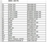
Some folks have asked for the BOM so am adding it and a simple schematic. Part numbers are Digi-key.
If someone who builds one of these boards has the ability to view/measure the before-and-after noise levels, I would be very interested to see the result.
Hi Wapo,
Search function is your friend, it has been measured at least twice by 2 different persons in the early part of this thread and results were very good.
Further, I can attest (as posted aswell) that it brought clear sonic benefits on different units (DAC, B1K etc.).
I am eager to try them on my VFET amp, one per channel, whenever I find the time to have a proper set up allowing quick comparisons.
I hope this helps
Claude
I had good success when I laid out a new PCB, optimized for testing. It was (the exact same layout of my RLC-RLC filter board) PLUS a pair of BNC jacks, for super low inductance ground connection between the board and the oscilloscope. The details are in post #515 of this thread, and here's what the board looked like. Click on the image to see it full size and undistorted.
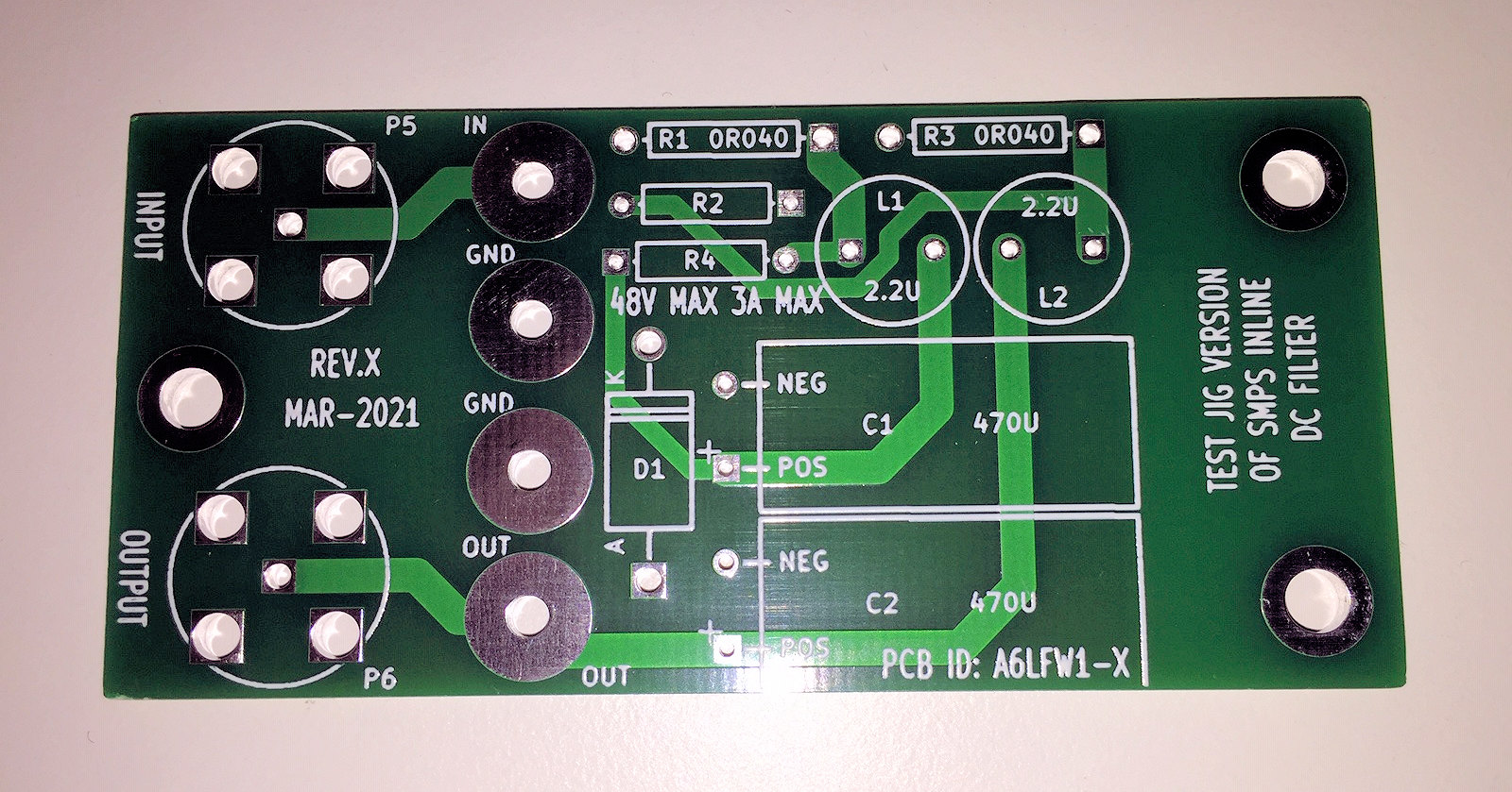
The left 25% of the board is the newly-added BNC jacks. You can see their connections to the filter input and output, while a solid ground plane on the bottom layer connects to all 4 ground pins of each jack. The right 25% of the board is empty dead space, whose only purpose is to surround and support the mounting bolts for this test fixture. The middle 50% of the board is the same exact layout as the normal RLC-RLC filter board. Exact same layout ---> exact same filtering performance. This PCB allowed me to take reasonable nice scope photos, see post #515.
If you do the same thing with your new filter PCB layout (posts #741 and #743), I imagine you'll get pretty clean scope photos, too.
Don't forget to connect a load resistor! The worst case condition for maximum SMPS noise, occurs when you pull lots of current from the SMPS output.
Best wishes for good results!
_
Last edited:
Hi Wapo,
Search function is your friend, it has been measured at least twice by 2 different persons in the early part of this thread and results were very good.
Further, I can attest (as posted aswell) that it brought clear sonic benefits on different units (DAC, B1K etc.).
I am eager to try them on my VFET amp, one per channel, whenever I find the time to have a proper set up allowing quick comparisons.
I hope this helps
Claude
I thought that including the quote about the Gerber and BOM for the dual voltage boards I laid out based on the Mean Well module would make clear that I was talking about actually testing those dual-voltage layouts, not the original filter design. Several people have expressed the intention of building them and was hoping one of those people would have the resources to verify their efficacy.
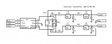
Some folks have asked for the BOM so am adding it and a simple schematic. Part numbers are Digi-key.
Thanks for this wapo..two/three questions (pardon if they sound like noob questions)..
1. What does R.C. represent on the input? The +&- represent the wallwart, yes?
2. What is the function of R11 and why is it not duplicated on the + rail?
Thanks,
Pete
Thanks for this wapo..two/three questions (pardon if they sound like noob questions)..
1. What does R.C. represent on the input? The +&- represent the wallwart, yes?
2. What is the function of R11 and why is it not duplicated on the + rail?
Thanks,
Pete
R.C. is from the Mean Well documentation -- means "remote control" -- if it floats or is positive, the module is active and if it's at negative, the module is turned "OFF."
R11 drops 6 volts at the specified current (as I recall, about 7mA) to drive the 24V coil from 30V. Note that the relay is a nominal 24V but the "must close" voltage is 18V so the relay will close when each leg of the power supply is around 9VDC. It works very well -- relay closes in well under a second but you can add way more capacitance than the power supply is rated for without triggering the short circuit protection.
Conveniently, the need for the resistor also allows the coil connection to "jump" the power connection on that side without breaking the lower plane with a trace.
")
Last edited:
Reference the pcb layout in post 742, that Mean Well module is not available in any voltage between 15V and 24V but I like this model for its relatively low noise and full metal shield so I don't want to switch. I am considering using the MW 24V module and adding an adjustable linear regulator onto the board to achieve +/- 18V for Wayne's BA2018 preamp. Even with the much larger module it could still be a lot smaller than a linear-only board with the same performance.
I'm wondering where to put that linear regulator -- my inclination is to put it between the MW module and the filter network but it's only an uneducated guess.
Is that a good idea or should the linears go last, after the MW and the filter?
If between, how small a capacitance and what kind of capacitance can/should I use between the MW and the linear? Does it matter much? I would guess not.
Any suggestions appreciated.
I would rather go for the following order:
SMPS - Filter - Linear reg if it has to be to drop voltage. Provided of course it is a linear reg and not a switching voltage converter.
Another approach for a circuit drawing a constant current could be SMPS - Filter (or included in the following) - additional R1CR2C filtering with a high R1 to drop the voltage down to the 18V you want... well noting that it is not exactly regulated then.
Have fun
Claude
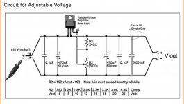
I used a different sequence when I threw together a wallwart-driven PS to power my Papa Pass H2V2 circuit (+12VDC input). I started with an 18V wallwart, then into the circuit below (not my creation) then into the PO89ZB then into the H2V2. I adjust the regulator while measure in voltage input at the H2V2 to give me exactly 12V. There’s obviously redundant filtering and capacitance but I’m not savvy enough to know what to alter when all three items are pieced together nor do I have a scope to see what’s happening. I figured the magical PO89ZB would cure anything bad that the regulator circuit may introduce and I think the H2V2 circuit has a bit of PS noise reduction built in already.
Gentlemen? Opinions?
Pete
Gentlemen? Opinions?
Pete
Attachments
Gentlemen? Opinions?
Pete
It appears that your overall circuit is as I suggested I would do --
smps -> linear reg -> po89zb.
It seems to me that the presence of the po89zb after everything else obviates the need for the capacitors downstream of the regulator in your drawing (as long as the po89 filter is not too far from the LM317).
- Home
- Source & Line
- Analog Line Level
- PO89ZB , an inline DC filter for SMPS wall warts . Preamps, HPA, Korg NuTube, etc