It's a religion thing. I generally "float" the mounting holes; they are electrically insulated from all other copper and all signals on the PCB. Other people do it differently.
Trial and error, uhh, that is, exhaustively thorough experimentation, often pays off handsomely in this case. Get out some alligator clip test wires and start short-circuiting the ground at point X to the ground at point Y. Which X-to-Y shorts are beneficial (e.g. reduce hum; reduce 120 Hz spikes on the THD plot, etc), and which shorts are detrimental?
_
_
Last edited:
@Thomas, wow, I have no idea where to put a BNC connection could you describe what you are suggesting?
I'm thinking about getting a new 'scope to replace the big old one I left behind when we moved recently but haven't done so yet and this would be a good excuse. Space is now limited so needs to be a modern small one, recommendations gladly accepted.") Rigol 200MHz 2-ch? 50Mhz 4-ch?
Rigol 200MHz 2-ch? 50Mhz 4-ch?
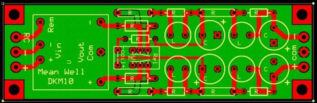
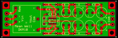
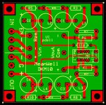
I like symmetry and found that I could move the first stage resistors to the outside edge of the pcb so have done so, and added my usual .150 standoff holes to the corners. Board had to grow to 4.125"
I'm thinking about getting a new 'scope to replace the big old one I left behind when we moved recently but haven't done so yet and this would be a good excuse. Space is now limited so needs to be a modern small one, recommendations gladly accepted.
Rigol 200MHz 2-ch? 50Mhz 4-ch?I like symmetry and found that I could move the first stage resistors to the outside edge of the pcb so have done so, and added my usual .150 standoff holes to the corners. Board had to grow to 4.125"
Attachments
Question on the above: Do you recommend the stand-offs contact the ground/return layer or be isolated so ground/return is only connected to the board via the specified connection points? I've seen this done both ways and you just reminded me that I've been curious about the pros/cons.
--Tom
I always insulate. Also, decided to separate the power input minus from the ground plane, leaving only the Mean Well output pin grounded to the plane along with the necessary component grounds and output ground.
Put everything on the red layer as best you can, and keep gigantic wide copper boulevards for electrons and holes to flow unrestrictedly, along the glassy smooth surface of the calm green lake.
_
The calm green lake is now unrestricted by traces.
Attachments
It's a religion thing. I generally "float" the mounting holes; they are electrically insulated from all other copper and all signals on the PCB. Other people do it differently.
Trial and error, uhh, that is, exhaustively thorough experimentation, often pays off handsomely in this case. Get out some alligator clip test wires and start short-circuiting the ground at point X to the ground at point Y. Which X-to-Y shorts are beneficial (e.g. reduce hum; reduce 120 Hz spikes on the THD plot, etc), and which shorts are detrimental?
_
That is a great idea. I've done that in the past to probe for points that alleviate ground-loops, but it had not occurred to me to do that on a functional circuit too!
--Tom
Mark...just got the really expensive kit from the store!! lol.
Took 5 minutes to complete...
Attached to my ACP + to one one of the back corner screws!
Really made a difference to me here...with HD650's
(also changed the resistors to make the ACP + pairing for 300 ohms).
I have never heard the 650's as nice as with this very, very simple and low cost setup.
Ingenius!
Alex
:>)
Attachments
![20210807_170614[42179].jpg](/community/data/attachments/883/883857-aa8b19a0f68ab2d2e822b816ccf2eec0.jpg)
![20210807_170623[42180].jpg](/community/data/attachments/883/883873-ccb16cc4199bad5c779ba26f81718680.jpg)
I have two types of 470uF capacitors, both recently purchased.
Nichicon UKW1V471MPD, ESR unpublished?
Kemet ESC477M035AH4AA, published ESR .039
I looked both at Mouser and Digi-key and could not find an ESR for the Nichicon.
Can someone tell me what is the ESR for the Nichicon? If not I'll just go with the Kemet. It's not ESR .015, but .039 is acceptable, I think.
I wonder why the Nichicon ESR is not published?
Calculating capacitor ESR from Tan(δ)
This might be helpful.
Calculating capacitor ESR from Tan(δ) - Tech Tips - Engineering and Component Solution Forum - TechForum │ Digi-Key
See first page of the Nichicon specs for Tan(δ) values.
This might be helpful.
Calculating capacitor ESR from Tan(δ) - Tech Tips - Engineering and Component Solution Forum - TechForum │ Digi-Key
See first page of the Nichicon specs for Tan(δ) values.
I have two types of 470uF capacitors, both recently purchased.
Nichicon UKW1V471MPD, ESR unpublished?
Kemet ESC477M035AH4AA, published ESR .039
I looked both at Mouser and Digi-key and could not find an ESR for the Nichicon.
Can someone tell me what is the ESR for the Nichicon? If not I'll just go with the Kemet. It's not ESR .015, but .039 is acceptable, I think.
I wonder why the Nichicon ESR is not published?
As Mark has pointed out a few times, you will find that if ESR values are not published, the ESR is unlikely to be in the "low" range. I'd go ahead and measure them (see the next post for instructions), but the best performance of this circuit is with the lowest ESR value caps we can reasonably find, which is why we ship the kits with either the KEMET ESH477M050AH4AA or the Nichicon 647-UHW1H471MPD. The Panasonic FM series are also acceptable, although they are not listed as "low ESR".
--Tom
I've been using the Panasonic EEU series, which are low ESR and are available at Mouser but are starting to run low stock
EEU-FR1H471B Panasonic | Mouser
EEU-FR1H471B Panasonic | Mouser
I have two types of 470uF capacitors, both recently purchased.
Nichicon UKW1V471MPD, ESR unpublished?
Kemet ESC477M035AH4AA, published ESR .039
I looked both at Mouser and Digi-key and could not find an ESR for the Nichicon.
Can someone tell me what is the ESR for the Nichicon? If not I'll just go with the Kemet. It's not ESR .015, but .039 is acceptable, I think.
I wonder why the Nichicon ESR is not published?
I've been using the Panasonic EEU series, which are low ESR and are available at Mouser but are starting to run low stock
EEU-FR1H471B Panasonic | Mouser
Those are listed as "Low ESR" and being Pani FM/FRs, measure out really well too.
--Tom
As Mark has pointed out a few times, you will find that if ESR values are not published, the ESR is unlikely to be in the "low" range.
--Tom
I'd not seen Mark's words on the subject but his thinking certainly coincides with my own intuitive interpretation of the absence of a rating.
I completely understand that the lowest ESR at 470uF is optimal for this filter, but there seems to be a tradeoff between low ESR and physical size.
Since I'm building a +/- circuit, size is important and I don't want four long capacitors lying on their sides taking up space. I keep in mind that Mark originally announced the circuit as working very well indeed with ESR .045 caps before he discovered that lower ESR capacitors made some improvement. I believe my Kemets at ESR .039 are as good or better ESR-wise as the capacitors were in the original circuit that worked well, so I'm going with those -- physically short enough to stand up in a low chassis to deliver clean power to my BA2018 which is going into a small diyaudiostore Korg B1 chassis along with another pcb that provides relay switched inputs and delayed output, and a 12v 25mA trigger circuit. So, 3 pcbs to fit in that small chassis, gotta keep it compact.
Yes great point; the caps have to fit on the board for your application. I ran into that when looking for alternatives to the Kemets with the required lead spacing and dimensions. The Kemets can be difficult to find in large quantities or even just available as some have found. There were some others that were in the low ESR zone but were too long or wide. If you don't mind not laying them down, you have some more options but Mark originally designed the board to fit in the little metal box (for shielding), so we wanted to use caps that preserved this constraint. The Kemets that come with the kit are the lowest ESR value we could find, but that does not mean you can't find lower.
Can't wait to see the pics of your BA2018
--Tom
So, just something that struck me and thought might be an interesting thing for someone to explore:
The Korg B1 and other Pass preamps have an RCRCRC smoothing system for the power supply. What if you replaced each R with an L-R combination as listed in the filter system and replaced each C with the filter's specified capacitance? Would the resulting pcb supply be smoother than the original RC chain?
Could we build the filter right on the preamp PCB without adding an additional board?
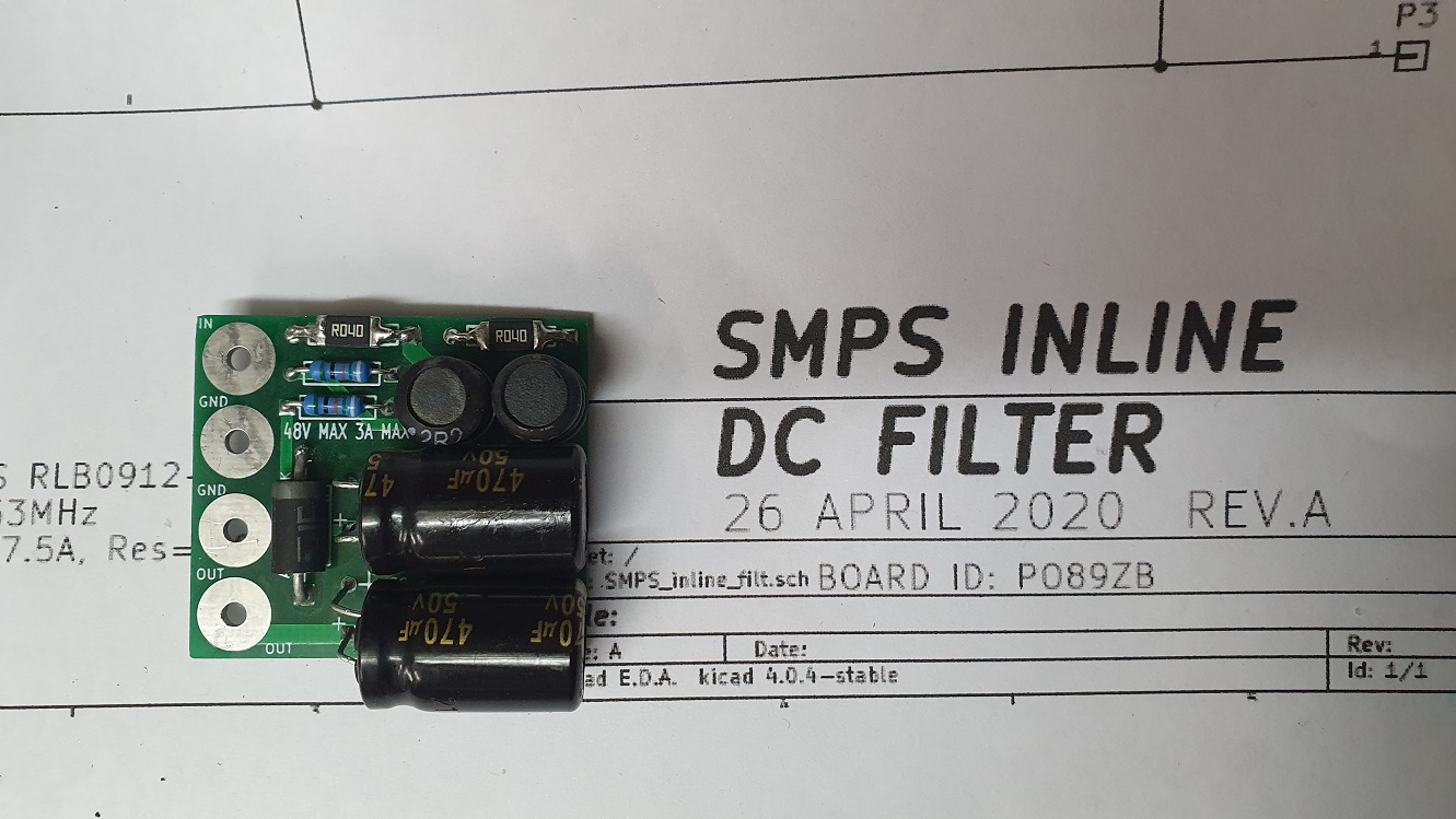
Finally got round to putting together one of these boards and thought I'd share the results.
The build was straight forward enough except:
* There were no through hole 0.04r current sense resistors available when I placed my latest parts order, so I squashed flat the end of some tinned solid core and made adapters for SMD parts.
* No mounting holes on this version of the board.
* The panasonic FM low ESR caps I had available were slightly too large.
Nothing insurmountable, and the board was a very quick to build.
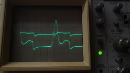
Next, I threw a 1Meg sine wave into the board. (Well, it used to be a sine wave before the long cables turned it into something fugly..):

~500mV went in at 1 MHz and 50mV came out.
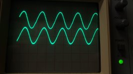
Next was a 100KHz (not so Fugly) sine:
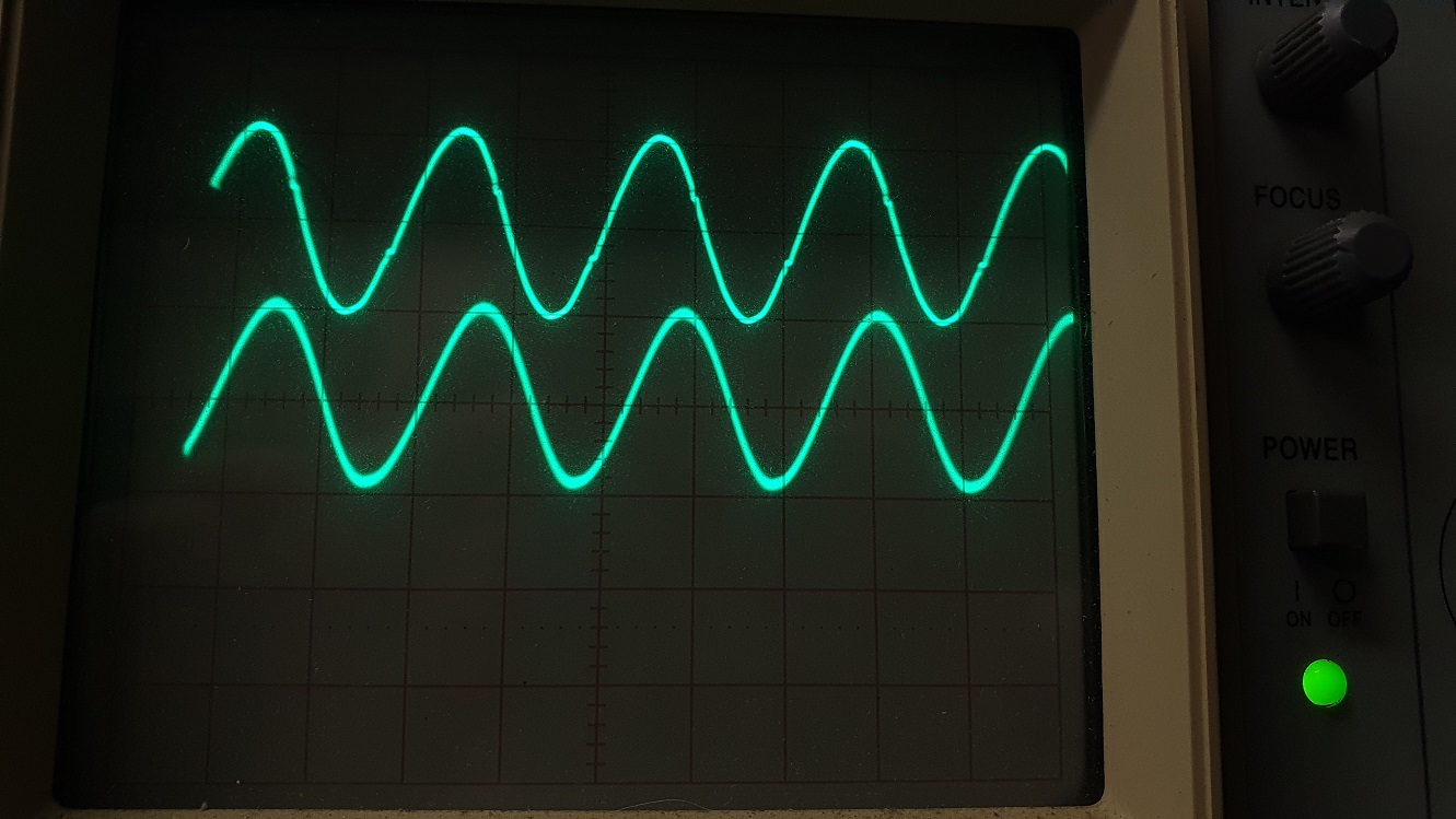
100mV in got 5mV out.
As you can see, I am using a CRO and not a fancy digital device capable of sweeps etc, but hopefully it illustrates that this filter is actually pretty good and doing what it is supposed to do.
As always, your mileage might vary, but I am happy with the results.
The build was straight forward enough except:
* There were no through hole 0.04r current sense resistors available when I placed my latest parts order, so I squashed flat the end of some tinned solid core and made adapters for SMD parts.
* No mounting holes on this version of the board.
* The panasonic FM low ESR caps I had available were slightly too large.
Nothing insurmountable, and the board was a very quick to build.
Next, I threw a 1Meg sine wave into the board. (Well, it used to be a sine wave before the long cables turned it into something fugly..):
~500mV went in at 1 MHz and 50mV came out.
Next was a 100KHz (not so Fugly) sine:
100mV in got 5mV out.
As you can see, I am using a CRO and not a fancy digital device capable of sweeps etc, but hopefully it illustrates that this filter is actually pretty good and doing what it is supposed to do.
As always, your mileage might vary, but I am happy with the results.
Attachments
Can't wait to see the pics of your BA2018
--Tom
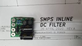
Finally got all the boards I need for my BA2018 preamp project. I tested the power supply with 1500uF on each leg (module rated at 330uF maximum) and I was at full voltage in less than one second with no glitching, I assume the relay is working flawlessly.
The filter board came out just about right except I didn't leave enough space inboard of the terminal blocks to include the needed text. Fixed in the next iteration.
Right now wishing I had a scope. There's a Tektronix TAS465 100 MHz Two Channel Oscilloscope on eBay that's five miles away for cheap ($127) but I gather that it is not a well-regarded instrument. Next choice might be a Siglent or Rigol from Amazon for quite a bit more. I really would like to see what quality of power I'm getting through the filter. Caps ESR rating is .039.
Attachments
Last edited:
Finally got all the boards I need for my BA2018 preamp project. I tested the power supply with 1500uF on each leg (module rated at 330uF maximum) and I was at full voltage in less than one second with no glitching, I assume the relay is working flawlessly.
The filter board came out just about right except I didn't leave enough space inboard of the terminal blocks to include the needed text. Fixed in the next iteration.
Right now wishing I had a scope. There's a Tektronix TAS465 100 MHz Two Channel Oscilloscope on eBay that's five miles away for cheap ($127) but I gather that it is not a well-regarded instrument. Next choice might be a Siglent or Rigol from Amazon for quite a bit more. I really would like to see what quality of power I'm getting through the filter. Caps ESR rating is .039.
There are lots of discussions about scopes/etc... but you'll find those two or Hanteks are really decent and fall in the amateur/mid-range lab quality range, which for what we're doing here is perfectly acceptable. My recommendation is to get one that has a built in signal generator as it simplifies things. Also look at some of the software-based solutions that utilize an external data acquisition hardware attached via USB such as the Focusrite Scarlet, or for a complete package take a look at QuantAudio. I just got the QA402 which is looking to be an awesome complete package much like there are other products that do the suite of tests on speaker drivers (and even automate them).
Theres also a ton of discussion and info over on the equipment and tools forum here:
https://www.diyaudio.com/forums/equipment-and-tools/
--Tom
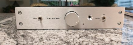
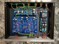
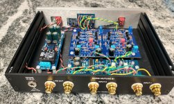
I wanted to build Wayne’s BA2018 preamp, and to save time and effort I decided to install it into my Korg B1 chassis, with a PO89ZB-based +/-15V power supply and my own pcb for delayed turn-on, relay-switched inputs, and a 12V 25mA Trigger circuit.
It all fit nicely into the 6.5” x 8.25” Korg chassis thanks especially to the PO89ZB power supply, along with a Muses chip-based IR remote controlled volume control and, surprisingly, I didn’t have to pack it in.
Sadly, it was going to be really tight to install a jack for the Trigger on the rear panel and since my current amp doesn’t have a trigger circuit, I decided to leave that capability for another project.
Attachments
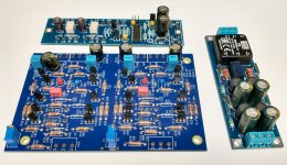
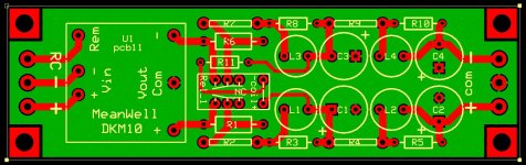
I don't know that anyone has any interest in a dual +/- supply from a single voltage and then smoothed by this filter, but thought I'd share my two layouts -- one a long rectangle to fit my B1 Korg chassis, and a more conventionally shaped 2.35"x2.35" square layout. The relay arrangement places a current-limiting resistor inline until the capacitors are mostly charged and then shorts the resistor. I can upload Gerbers if anyone wants them.
Attachments
- Home
- Source & Line
- Analog Line Level
- PO89ZB , an inline DC filter for SMPS wall warts . Preamps, HPA, Korg NuTube, etc