!!!!!
Many thanks for your kind reply, Mark.
I am not familiar with SMPS, so I am thankfull I learned something and I will now try to dig a similar paper on the exact Meanwell SMPS I use.
This might be an interesting read before measurements, eventhough in my B1K the load is presumably quite constant (but far from full load, wether that's better or worst). Other components I have present clearly a dynamic load at varying frequencies depending on music material, so... ouch!
One can see on Mark's link how things can move from a 150mV p-p spec (I presume constant full load) to a 2800mV p-p spec under (given) dynamic conditions, eventhough the said Meanwell performs well within these specs with much better values...
On this unit they performed (some) tests, the ripple varies by factor 10 depending on the load cycle... and can here under dynamic loads tripple the value of the usual max advertised ripple & noise :-(
Thanks again, Mark!
Claude
Turns out Meanwell's reports are sadly less detailled regarding dynamic load behaviours when it comes to SGA25E24-P1J
Whatever, Mark's filter deserves maximum consideration. I will move it outboard again from my B1K casing, considering it as a single component with a lot of sonic added value. This position will help me playing with it... or them when daisy chaining. And possibly having a look at what the oscilloscope says at various points, while at it...
Good the small filters are all in casings ready to be plugged
Stay safe
Claude
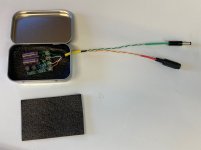
I put one together for use with my B1 Korg NuTube today, thanks rikiheck for the boards and Mark for the design. Mouser didn't have either the Nichicon or the Kemet caps in stock when I ordered so I went with United Chemi-Con low-ESR electrolytics, 661-EKYA500E471MJ25S, as well as some fancier EPCOS/TDK caps that I'm not sure I'll use for this. Unfortunately I only ordered two of the Bourns inductors instead of four so the second board will stay incomplete for now. Using a larger tin because that's what I had.
I set it up to be external to my B1 Korg while I evaluate it. Right now, I feel like the sound is brighter and possibly more detailed, but a lot more listening is in order.
I set it up to be external to my B1 Korg while I evaluate it. Right now, I feel like the sound is brighter and possibly more detailed, but a lot more listening is in order.
Attachments
Mark, I have put your fine filter inline between the SMPS wall-wart and the Korg pcb of Nelson Pass's Korg preamp. Seems to work wonderfully well.
I am now faced with installing a SMPS board to split the +24vdc into +/- 15vdc so that I can install an IR volume control of equal quality.
Does your filter exist in a compact +/- configuration or could such a configuration be easily created?
I am now faced with installing a SMPS board to split the +24vdc into +/- 15vdc so that I can install an IR volume control of equal quality.
Does your filter exist in a compact +/- configuration or could such a configuration be easily created?
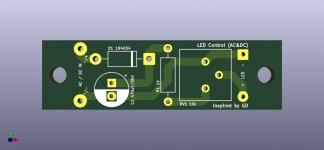
audiosy.net's Modified LED Board From Carsten Witt
Simple AC-DC LED rectifier for power on indicator – audiosy.net
I ask Carsten to add mounting holes to ausiosy.net LED Board and he was kind enough to send me the files.
I also contacted audiosy.net and received this email:
Looks good. Please feel free to post but please put a link to my site in you're post if you don't mind.
Regards
Gareth
I have reached out to audiosy.net but no response as of yet...
Simple AC-DC LED rectifier for power on indicator – audiosy.net
I ask Carsten to add mounting holes to ausiosy.net LED Board and he was kind enough to send me the files.
I also contacted audiosy.net and received this email:
Looks good. Please feel free to post but please put a link to my site in you're post if you don't mind.
Regards
Gareth
Attachments
....I am now faced with installing a SMPS board to split the +24vdc into +/- 15vdc so that I can install an IR volume control of equal quality.
Does your filter exist in a compact +/- configuration or could such a configuration be easily created?
Why not use two boards; Populate one normally (Positive Supply) and on the other board, reverse the polarity of the tranzorb diode and capacitors (Negative supply)?
Attachments
Why not use two boards; Populate one normally (Positive Supply) and on the other board, reverse the polarity of the tranzorb diode and capacitors (Negative supply)?
Yes, have thought of that, but also wondered if a purpose-specific board could be made smaller. The Korg preamp is pretty space-limited, the +/- is needed for an IR-capable volume control. The splitter SMPS is commercially available but an output filter is needed.
Last edited:
Also, if you do populate a negative supply board, make sure to label it negative supply (white sticker?).
One can design a PCB for pos/neg supply, but I do not think one has been made, as of yet.
I have been poking around with KiCAD, but there is a learning curve for that software. After using Cadence IC design/layout and SPICE simulation for many years, I am bit spoiled. Even TINA (SPICE) takes a while to get used to.
Last edited:
Stack two boards vertically. Since the electrolytic capacitors are laid sideways (flat), the height of each board is quite small. 2 x (small height) = small total height.
Extremely useful accessories from Amazon
_
Extremely useful accessories from Amazon
_
Last edited:
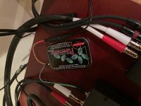
Very nice! The pretty artwork on the box, and the good long pieces of protective heatshrink tubing, make for a handsome result. Congratulations!
Thanks, Mark. I'm tempted to try one of these on my RPi/DAC but the RPi I use, a 3b, is extremely fussy about input voltage, and I'm worried that the voltage drop over the PO89ZB will irritate it. The wall wart I use is the official RPi one rated 5.1V 3A for the 4th gen Pi's. The 3b throws undervoltage errors with lesser 5V rated wall warts. Anyway, just rambling. Not sure using the PO89ZB is solvable without a different regulated supply. Unless maybe I only power the DAC with it?
I have one PO89ZB pcb at the moment, has anyone used one of these to run two devices?
In this case I have a Korg B1 and a Bugle 2, both of which draw I am almost positive well under 200mv. The SMPS I have is 750 mv @ 24v.
Could I use that to run both? Clearly both run off an SMPS, so it seem like filtering just one won't be as effective.
In this case I have a Korg B1 and a Bugle 2, both of which draw I am almost positive well under 200mv. The SMPS I have is 750 mv @ 24v.
Could I use that to run both? Clearly both run off an SMPS, so it seem like filtering just one won't be as effective.
PO89ZB only filters out noise on its INPUT port. If you connect (N > 1) loads to its OUTPUT port, and if one or both of those loads creates noise on its power supply, PO89ZB won't filter it. Load#1 may create noise which Load#2 does not like, and vice versa.
However: the Korg B1 and the Hagerman Bugle2 are all-analog devices. They are unlikely to create noise on their power supply. So it's not likely that B1 will pollute Bugle2's supply, and vice versa. The odds are good that your experiment will succeed.
On the other hand, WHY NOT give each of them its own PO89ZB? The boards are small and the components are cheap.
You could even go kamikaze, and deploy three PO89ZBs if you wanted King Of The Hill bragging rights:
Code:
               +--------+            +--------+       +-------+
     SMPS----->|Filter#1|------O---->|Filter#2|------>|Korg B1|
               +--------+      |     +--------+       +-------+
                               |
                               |
                               |     +--------+       +-------+
                               +---->|Filter#3|------>|Bugle 2|
+--------+ +-------+You could even go kamikaze, and deploy three PO89ZBs if you wanted King Of The Hill bragging rights:
Code:+--------+ +--------+ +-------+ SMPS----->|Filter#1|------O---->|Filter#2|------>|Korg B1| +--------+ | +--------+ +-------+ | | | +--------+ +-------+ +---->|Filter#3|------>|Bugle 2| +--------+ +-------+
That's crazy enough it just might work!! The only reason is because I have the one PCB and didn't see a place to find more. Also thanks for the response.
Does anyone have PCBs, or would be interested if I put in an order?
That's crazy enough it just might work!! The only reason is because I have the one PCB and didn't see a place to find more. Also thanks for the response.
Does anyone have PCBs, or would be interested if I put in an order?
If you can wait I am sending about 100 kits to the store today or tomorrow.
--Tom
")
See post #514 if you prefer to suffer ANY hardships in exchange for the convenience of not having to order boards yourself. Or buy them from the diyAudio Store as mentioned in post #536.
_
Having been the recipient of Mark's generous help on this and successfully ordered boards, I am happy to help offload questions on that if anyone that needs help with Mark's instructions in post #536. Please contact me offline.
--Tom
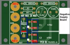
Here's a bipolar PCB layout. Boards are still on their way to me, so I have not verified the layout with actual parts yet. Caps are Panasonic EEU-FR1H471B
EEU-FR1H471B Panasonic | Mouser
There is room to lay them down to save 7.5mm in height if desired.
Boards are 57mm X 86mm. You can get a 5 pc. order for under $9 delivered, if you are willing to wait 2 - 3 weeks for standard freight. Double that price if you want them in just a few days.
EEU-FR1H471B Panasonic | Mouser
There is room to lay them down to save 7.5mm in height if desired.
Boards are 57mm X 86mm. You can get a 5 pc. order for under $9 delivered, if you are willing to wait 2 - 3 weeks for standard freight. Double that price if you want them in just a few days.
Attachments
- Home
- Source & Line
- Analog Line Level
- PO89ZB , an inline DC filter for SMPS wall warts . Preamps, HPA, Korg NuTube, etc